background image

OPERATING INSTRUCTIONS

29

M200–LV  M250–LV

–CURRENT STATUS–

barg

7,5

barg

PACKAGE DISCHARGE TEMP

39,4

_

C

RUNNING UNLOADED

AIREND DISCHARGE TEMP

MODE: MOD/ACS

89,4

_

C

WARNING

MAIN MENU

Pressing the WARNING button will return the display to the

WARNING screen and the RESET button.

A Warning needs to be reset by the operator by pressing the RESET

button twice.

The possible Warning messages are as follows;

AIREND DISCHARGE TEMP  This will occur if the Airend Discharge
(2ATT) exceeds 97% of the alarm limit, 228

_

F (109

_

C) and is not

adjustable.

CHANGE COOLANT FILTER  This warning will occur if the high side
pressure is 20 psig (1,4 bar) greater than the low side pressure of 1
DPS and the Injected Coolant temperature (2CTT) is greater than
120

_

F (49

_

C).

CHANGE INLET FILTER  This will occur if the Inlet Vacuum (1AVPT)
is greater than 0,7 psig (0,05 bar) and the machine is fully loaded (inlet
valve is completely open).

CHANGE SEPR ELEMENT  This warning will occur if the pressure
on the Separator (3APT) is 15 psig (1,0 bar) greater than the pressure
at the Package Discharge (4APT) and the machine is fully loaded.
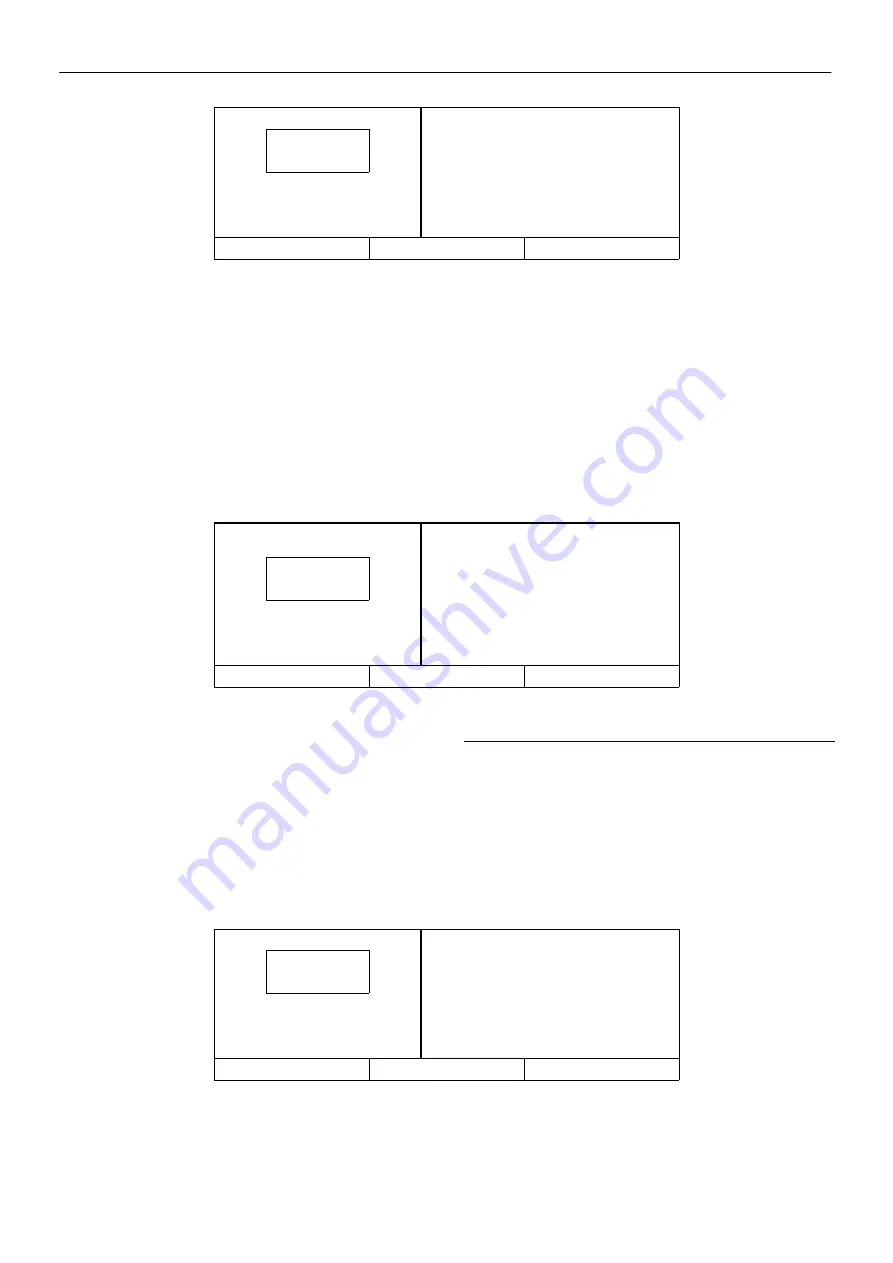
ALARM

barg

7,5

barg

HIGH AIREND DISCH TEMP

109,4

_

C

STOPPED BY ALARM

MODE: MOD/ACS

PRESS RESET TWICE

STATUS

MAIN MENU

RESET

HIGH DISCHARGE PRESS  This can occur if the machine’s loading
function is being controlled by a host device such as a sequencer or an
ISC. This warning will occur when the package discharge pressure is
above the maximum offline pressure (rated pressure plus 3 psig (0,2
bar)) for more than 3 seconds. This warning will cause the compressor
to unload. The host device will not be able to load the compressor until
the package discharge pressure falls to the rated pressure of the
machine.

SENSOR FAILURE 4ATT  This will occur if the Package Discharge
Temperature Sensor (4ATT) is missing or broken.

ALARMS

When an Alarm occurs, the word ALARM will flash on the display

screen and appear in large letters as shown above. The display
message will indicate what caused the Alarm.

Pressing the STATUS button will display the STATUS screen. The

presence of the ALARM button indicates that an Alarm condition still
exists. Alarm Status is the list of machine operating conditions that
existed at the time of the Alarm.

–ALARM STATUS–

barg

7,5

barg

PACKAGE DISCH PRESSURE

7,5 barg

STOPPED BY ALARM

PACKAGE DISCHARGE TEMP

MODE: MOD/ACS

39,4

_

C

ALARM

MAIN MENU

The name and value of each of the items listed can be seen by

moving the list up and down using the arrow buttons. Pressing the
ALARM button will return the display to the Alarm screen and the
RESET button.

The Alarm needs to be reset by the operator by pressing the RESET

button twice. Any exceptions to this are explained in the alarm
descriptions.

The possible Alarm messages are as follows;

CHECK INLET CONTROL  This will occur if the machine is unloaded
and the inlet vacuum is less than 3 psig (0,2 bar).

Содержание M200-LV

Страница 1: ...M200 2440110 OPERATION AND MAINTENANCE MANUAL This manual contains important safety information and must be made available to personnel who operate and maintain this machine C C N 22071393 en REV A D...

Страница 2: ...NGERSOLL RAND COMPANY LIMITED SWAN LANE HINDLEY GREEN WIGAN WN2 4EZ UNITED KINGDOM DECLARE THAT UNDER OUR SOLE RESPONSIBILITY FOR MANUFACTURE AND SUPPLY THE PRODUCT S M200 LV M250 LV TO WHICH THIS DEC...

Страница 3: ...ion NR Not required AR As required SM Sitemaster Sitepack HA High ambient machine WC Watercooled machine AC Aircooled machine ESA European serviced areas ERS Energy recovery system T E F C Totally enc...

Страница 4: ...e right to make changes and improvements to products without notice and without incurring any obligation to make such changes or add such improvements to products sold previously The intended uses of...

Страница 5: ...risk WARNING Air gas flow or Air discharge X XBAR WARNING Pressurised component or system WARNING Hot and harmful exhaust gas WARNING Maintain correct tyre pressure Refer to the GENERAL INFORMATION s...

Страница 6: ...o not remove the Operating and Maintenance manual and manual holder from this machine Do not stack Do not operate the machine without the guard being fitted Do not stand on any service valve or other...

Страница 7: ...re operation or maintenance of this machine is undertaken When parking use prop stand handrake and wheel chocks Contains asbestos SET SEQUENCER STATUS LOAD SEQUENCER AUTOMATIC CONTROL COMPRESSOR OFF L...

Страница 8: ...ISED TANK ON OFF CYCLE COOLANT FILTER AIR FILTER ON OFF PUSH BUTTON COOLANT PRESSURE AIR PRESSURE STAR DELTA IEC 617 7 AUTOMATIC RESTART HEAT EXCHANGER MAINTENANCE MAINTENANCE PROHIBITED COOLANT DRAIN...

Страница 9: ...ISO SYMBOLS 7 M200 LV M250 LV BELT TENSION FILTER MOTOR LUBRICATION FRAGILE KEEP DRY THIS WAY UP USE NO HOOKS NO SIDE CLAMPS ROTATION POWER INLET AC WATER IN WATER OUT...

Страница 10: ...ected to the machine must have safe working pressure ratings of at least the machine rated pressure If more than one compressor is connected to one common downstreamplant effective check valves and is...

Страница 11: ...re compatiblewith its electrical characteristics and that are within it s rated capacity Condensate disposal Condensate cannot be discharged into fresh surface water drains In some regions compressor...

Страница 12: ...C LUBRICATION SYSTEM AIR COOLED MACHINES KEY A LUBRICANT B LUBRICANT AIR 1 COOLER 2 SEPARATOR TANK 3 FILLER PLUG 4 ORIFICE SCREEN 5 SAFETY VALVES 6 COOLANT STOP VALVE 5SV 7 COOLANT FILTER 8 THERMOSTAT...

Страница 13: ...0 LV WC LUBRICATION SYSTEM WATER COOLED MACHINES KEY A LUBRICANT B LUBRICANT AIR 1 COOLER 2 SEPARATOR TANK 3 FILLER PLUG 4 ORIFICE SCREEN 5 SAFETY VALVES 6 COOLANT STOP VALVE 5SV 7 COOLANT FILTER 8 TH...

Страница 14: ...AIR PIPING AIR COOLED MACHINES KEY A AIR B LUBRICANT AIR 1 AFTERCOOLER 2 SEPARATOR TANK 3 COMPRESSOR 4 CHECK VALVE 5 BLOWDOWN VALVE 3SV 6 PRESSURE TRANSDUCER 7 MOISTURE SEPARATOR OPTION 8 MINIMUM PRES...

Страница 15: ...KEY A AIR B LUBRICANT AIR 1 AFTERCOOLER 2 SEPARATOR TANK 3 COMPRESSOR 4 CHECK VALVE 5 BLOWDOWN VALVE 3SV 6 PRESSURE TRANSDUCER 7 MOISTURE SEPARATOR OPTION 8 COOLER 9 MINIMUM PRESSURE VALVE 10 SAFETY V...

Страница 16: ...tic valve and a filter When the unit is operating the coolant is pressurised and forced to the compressor bearings The compressor load control system is automatic On Off line The compressor will opera...

Страница 17: ...43 9 m3 min 1550 ft3 min 42 5 m3 min 1501 ft3 min 38 8 m3 min 1370 ft3 min FULL LOAD CURRENT MAXIMUM 380V 557 538 FULL LOAD CURRENT MAXIMUM 415V 536 519 STARTING CURRENT MAXIMUM 380V 1020 1020 STARTIN...

Страница 18: ...GENERAL INFORMATION 16 M200 LV M250 LV Revision A 22158653 AC...

Страница 19: ...in contactor KM2 Delta contactor KM3 Star contactor KM4 Fan contactor MM Main motor FM Fan motor TR Thermistor relay motor windings MOL Main motor overload relay RFI RFI filter PCB1 Printed circuit bo...

Страница 20: ...GENERAL INFORMATION 18 M200 LV M250 LV Revision A 22065734 WC...

Страница 21: ...2 Delta contactor KM3 Star contactor KM4 Fan contactor MM Main motor FM Fan motor TR Thermistor relay motor windings MOL Main motor overload relay RFI RFI filter PCB1 Printed circuit board Power suppl...

Страница 22: ...of the compressor are slots to enable a fork lift truck 5 ton minimum to move the machine Alternatively a special lifting frame can be supplied to enable a crane or hoist to move the compressor LOCATI...

Страница 23: ...olts and spacers which are marked with fluorescent tags Two are situated on the airend support and the other two on the motor support ELECTRICAL DATA An independent electrical isolator should be insta...

Страница 24: ...ally with damage to the system Scale Scale formation inhibits effective heat transfer yet it does help prevent corrosion Therefore a thin uniform coating of calcium carbonate is desired on the inner s...

Страница 25: ...ESSURE is less than the ONLINE PRESSURE This also returns the machine to the operating mode that is specified by the MODE OF OPERATION set point The other five buttons provide access to various operat...

Страница 26: ...ighted This means that they are displayed as light characters on a dark background barg CURRENT STATUS 7 5 barg PACKAGE DISCHARGE TEMP 39_C RUNNING LOADED AIREND DISCHARGE TEMP MODE MOD ACS 89_C MAIN...

Страница 27: ...tions Items will be highlighted in inverse display mode 1 Selecting the highlighted item will display the corresponding menu 2 Selecting the highlighted item will place the value in edit mode This is...

Страница 28: ...SEC Screen Contrast 0 to 10 1 Does not apply to automatic across the line starters OPERATOR SETPOINTS barg 7 5 barg OFFLINE PRESSURE 7 6 barg READY TO START ONLINE PRESSURE 6 9 barg STATUS MAIN MENU S...

Страница 29: ...ENSOR 1AVPT CALIBRATE READY TO START SENSOR 3APT CALIBRATE STATUS MAIN MENU SELECT SENSOR CALIBRATION Pressure sensor calibration is done through the SENSOR CALIBRATION screen Sensor calibration can o...

Страница 30: ...and value of each of the items listed below can be seen by moving the list up and down using the arrow buttons Pressing the ALARM HIST button will return the display to the ALARM HISTORY screen ALARM...

Страница 31: ...a sequencer or an ISC This warning will occur when the package discharge pressure is above the maximum offline pressure rated pressure plus 3 psig 0 2 bar for more than 3 seconds This warning will ca...

Страница 32: ...ontains unacceptable values When this occurs the sensors should be calibrated and all the set points checked It is normal for this alarm to occur after changing controller software REMOTE START FAILUR...

Страница 33: ...itch STOPPING THE MACHINE IN AN EMERGENCY Refer to the diagram T5443 If the machine has to be stopped in an emergency DEPRESS THE EMERGENCY STOP BUTTON 1 LOCATED ON THE INSTRUMENT PANEL This will over...

Страница 34: ...ough optimization and efficiency and reduced produc tion losses through fewer unexpected maintenance requirements and downtime An optional feature Intelliguard is used to reduce downtime by remote mon...

Страница 35: ...r 1000 hours or as defined by local or national legislation Separator tank Fully inspect all external surfaces welds and fittings Report any excessive corrosion mechanical or impact damage leakage or...

Страница 36: ...signs indicating that Maintenance Work is in Progress are posted in a position that can be clearly seen Upon completion of maintenance tasks and prior to returning the machine into service ensure that...

Страница 37: ...ny form of sealant on either the separator tank or the separator tank cover faces WARNING Do not remove the staple from the anti static gasket on the separator element since it serves to ground any po...

Страница 38: ...shows OVERPRESSURE BLOWDOWN SYSTEM Check the operation of the load solenoid OVERPRESSURE INEFFECTIVE Check the operation of the unloader valve strip and clean if necessary Compressor will not DEMAND...

Отзывы: