


45530110_ed1
5
NOTICE
This is a left-hand thread.
At the middle of the Clutch Housing threads, apply Loctite
Threadlocker 3 Bond 1406® to about three threads. Push down and
rotate the Bit Holder until it engages the Cam Guide. Hold in place.
Screw the Clutch Housing in completely.
25. Using an open end torque wrench on the flats of the Clutch
Housing, tighten the Clutch Housing to 28.5 Nm.
26. Apply grease to both ends of the Clutch Pilot Rod (38) and insert
it into the Gear Case.
27.
For Throttle Lever Start Models
, inspect the clearance of the Bit
Holder Assembly. Touch the end of the Clutch Pilot Rod and push
on the Bit Holder Assembly. If the Clutch Pilot Rod is moved by
the Bit Holder at this time, add additional spacers.
28. Install the Bit Retainer Retaining Ring (10), sharp edge side first,
into the second groove from the bit end of the Bit Holder.
29. Apply grease to the holes of the Bit Holder and insert the two Bit
Retaining Balls (19) into the holes.
30. Apply grease to one end of each Clutch Adjusting Pin (11) and
insert the three Pins into the Clutch Housing.
31. Apply grease to the other end of each Clutch Adjusting Pin and
the threads of the Clutch Housing. Screw the Clutch Adjusting
Ring (4) onto the Housing.
32. Install the Bit Retainer Sleeve (9), the Bit Retainer Spring (8) and
the Bit Retainer Collar (7) onto the Bit Holder.
33. Using a thin blade screwdriver, install the Front Bit Retainer
Retaining Ring (6).
34. Unclamp the Gear Case Jig from the vise and turn it over to
remove the Clutch and Gear Case Assembly.
35. Lift the Motor slightly and slide the Gear Case onto Motor with
the Ground Screw hole adjacent to the ground wire.
36. Attach the ground wire to the Gear Case with the Ground
Screw (74) and Washer (75). Tighten to 4 KG-cm.
37. Turn the Gear Case until the notch in the Gear Case matches the
tab in the Housing.
38. Completely insert the ground wire into the groove in the
Housing.
Adjusting the Brake Timing
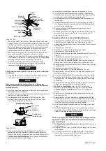
Insert a .65 mm thick gauge or pin gauge between the Pilot Rod
Adjusting Screw (55) head and the Shut-off Switch. Push the Bit
Holder.
The Shut-off Switch should not click.
1.
Insert a .80 mm gauge and push the Bit Holder.
The Shut-off
Switch should click.
Adjust the Pilot Rod Adjusting Screw if necessary using the two
adjusting spanner wrenches.
For Throttle Lever Start Models,
there is no need to push the Bit
Holder, Slide the gauges between the Pilot Rod Adjusting Screw
and the Throttle Lever (76).
Assembly of the Tool
For Push to Start Models,
make sure the ground wire is inserted
in the groove in the Housing.
For Throttle Lever Start Models,
make sure the Ground Wire is
between the Motor Assembly and the Housing.
Snap the Housing halves together.
For Throttle Lever Start Models,
insert the Throttle Lever Pin
(78) into the Housing. Insert the Throttle Spring (77) into the
Throttle Lever. While compressing the Throttle Spring, install
the Throttle Lever onto the Throttle Lever Pin. Snap the Housing
halves together.
Install the Housing Screws (83) into the Housing and tighten to
4 KG-cm.
Slide the Flange (2) onto the Housing. Screw the Retainer
Coupling (1) onto the Housing until it clicks into place.
NOTICE
These are left-hand threads.
7. Attach the Power Cord (81 or 84).
Testing the Tool
Test forward and reverse operation by pressing the Bit Holder
against the work surface with the Reverse Switch in each position.
Tighten the Clutch Adjusting Ring all the way, reverse it one turn
and test for proper shut off operation and maximum torque.
Reset the Clutch Adjusting Ring to mid scale and check for torque
repeatability by cycling the tool between five to ten times.
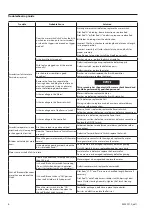
For repair and troubleshooting of the high torque low voltage
Controller, refer to the operation and maintenance manual.
2.
3.
4.
1.
2.
3.
4.
5.
6.
1.
2.
3.
4.
(Dwg. TPD1821-1)


