


2
45530110_ed1
WARNING
Always wear eye protection when operating or performing maintenance on this tool.
Always turn off the air supply and disconnect the air supply hose before installing, removing or adjusting any accessory on this tool or
before performing any maintenance on this tool.
Note:
When reading the instructions, refer to exploded diagrams in parts Information Manuals when applicable (see under Related Documentation
for form numbers).
Disassembly
Disassembly of the Housing
Unplug the Power Cord (84) from the wall socket. Unscrew the
connection ring and set the cord aside.
Unscrew the Retainer Coupling (1) and remove the Flange (2).
NOTICE
This is a left-hand thread.
3. Lay the tool on the workbench with the Brush Light Plate (80)
side down and remove the Housing Screw (83) using a #1 phillips
screwdriver.
4. Insert a thin blade screwdriver into the two notches and carefully
pry the two halves of the Housing Package (79) apart.
For Throttle Lever Start Models,
remove the Throttle Lever (76),
Throttle Spring (77) and Throttle Lever Pin (78).
Disassembly of the Clutch Housing and Gear Case
Tilt the Clutch Housing (12), Gear Case (36) and Motor Assembly
upward slightly and turn the Gear Case until the Ground
Screw (74) shows.
NOTICE
Be sure to hold the Motor Assembly and Gear Case together.
Rough handling may damage the Fan Pilot Rod (40) in the
Fan (41).
2. Using a phillips screwdriver, remove the Ground Screw and the
Ground Screw Washer (75).
3. Remove the Clutch Housing and Gear Case from the Housing.
When removing the Gear Case from the Housing, hold the Gear
Case Shield (37) so that the Gears do not fall out.
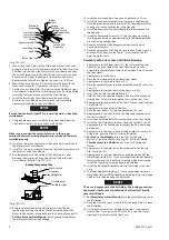
4. Remove the Fan (41) and the Fan Pinion Gear (39). Remove the
Fan Pilot Rod (40).
NOTICE
The Fan Pilot Rod is ceramic. Do not mishandle or drop.
5. Remove the Gear Case Shield and drop the two Spindle/Gear
Heads (31) from the Gear Case.
6. Separate the Spindle/Gear Heads and remove the Gear head
Pinion Gear (35) and Planet Gears (34).
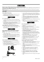
7. Fit the two notches at the rear of the Gear Case into the Gear Case
Jig part no. EP1510N-J37. (Refer to Dwg. TPD1820)
8.00
31.20
5.90
5.85
31.10
clockwise
(Dwg. TPD1820)
1.
2.
1.
8. Using a thin blade screwdriver, remove the Front Bit Retainer
Retaining Ring (6) from the Bit Retainer Sleeve (9). Remove the Bit
Retainer Collar (7), the Bit Retainer Spring (8) and the Bit Retainer
Sleeve.
9. Remove the two Bit Retaining Balls (19) from the Bit Holder
Assembly (21) by tapping the Housing on the work surface.
10. Unscrew the Clutch Adjusting Ring (4) and remove the three
Clutch Adjusting Pins (11).
11. Using external snap ring pliers, remove the Bit Retainer Retaining
Ring (10).
12. Using a 29 mm wrench on the flats of the Clutch Housing,
unscrew and remove the Clutch Housing from the Gear Case.
NOTICE
This is a left-hand thread.
13. Remove the Clutch Spring Plate (15) and the Clutch
Spring (16).
14. Remove the Taper Ring Retaining Ring (17).
15. Remove the Bit Holder Assembly and separate it from the Taper
Ring Assembly (18).
16. Remove the two Pilot Cam Balls (20), the Pilot Push
Spring (23), the Pilot Push Spring Washer (22) and the Pilot (22)
from the Bit Holder Assembly.
17.
For Throttle Lever Start Models,
remove the Front
Shim (13) and the Rear Shim (14) first. Then remove the Taper
Ring Retaining Ring. Separate the Taper Ring Assembly from the
Bit Holder. Remove the two Pilot Cam Balls and the Pilot (22) from
the Bit Holder Assembly.
18. Remove the Clutch Pilot Rod (38) and the Cam Guide (24).
Remove the two Cam Guide Balls (25) from the Guide.
19. Lift the Gear Case from the Gear Case Jig and push the Spindle
Bearing (30) and Cam (27) from the Case.
20. Lift the Cam from the Spindle Bearing and remove the Cam
Rollers (28).
21. Slide the Spindle Washer (29) from the Spindle Bearing.
Cleaning and Inspection of the Tool
Clean all of the mechanical parts in an approved safety solution in
a well-ventilated area. Inspect for damage or wear.
Inspect the Fan. If the four corners of the hole are worn, replace
the Fan.
Inspect the Fan Pinion Gear and Fan Pilot Rod. If they are
damaged or cracked, replace them.
If the taper on the Pilot is worn, replace the Pilot and the two Pilot
Cam Balls.
Inspect the Cam Guide Balls. If they are worn, replace them.
Inspect the Cam Guide. If its holes are worn, replace it.
Inspect the Taper Ring Assembly. If the internal taper is worn,
replace it.
Inspect the Cam Rollers. If they are worn, replace them.
Inspect the Spindle Washer. If the surface is worn, replace it.
Inspect the Spindle Bearing. If it does not rotate smoothly,
replace it.
Inspect the Gears and the Gear Case. If the teeth are worn, replace
them.
1.
2.
3.
4.
5.
6.
7.
8.
9.
10.
11.


