


45530110_ed1
3
Disassembly of the Electrical Components
Remove the Reverse Switch Circuit Board (69) from the Housing.
NOTICE
Do not touch any circuit paths if using pliers.
2. Loosen the Receptacle Assembly (73).
3. Using a #0 phillips screwdriver, remove the two Switch Base
Screws (63) mounted on the Microswitch Circuit Board (58).
NOTICE
The Switch Base Screws are coated with thread adhesive.
Unscrew gradually to prevent damage to the threads.
4. Remove the Motor Assembly and the Controller Assembly (68)
from the Housing Package while holding both of them together.
NOTICE
Be careful not to damage the Motor Pilot Rod (42).
5. To remove the Controller Assembly, pull the three pin connector
from the Reverse Switch Circuit Board.
6. Remove the two-pin connector from the Microswitch Circuit
Board.
7. Using needle nose pliers, remove the three wires from the Shut-
off Switch (60).
NOTICE
Be careful not to damage the Shut-off Switch Terminals.
8. Set the Controller Assembly aside.
9. Grasp the Microswitch Circuit Board using needle nose pliers and
squeeze the ends of the two white Switch Base Spacers (65).
10. Using needle nose pliers, squeeze the Switch Base Spacers and
remove the Insulating Film (66).
11. Using the pliers, remove the Switch Base Spacers from the Brush
Light Circuit Board.
12. Remove the two Shut-off Switch Screws (62).
13. Remove the two Start Switch Screws (62).
14. Remove the Switch Plate (59) and the Switch Pilot Rod (56) from
the Switch Plate.
15. Inspect the tip of the Switch Pilot Rod. If it is bent or worn,
replace it.
16. Check the Shut-off Switch for continuity. Replace it if defective.
17. Check the Start Switch (61) for continuity. If it is defective,
desolder and remove it from the Microswitch Circuit Board.
18. If the Brush Light Circuit Board is defective, desolder and remove
the red and blue wires.
19. If the components on the Reverse Switch Circuit Board are
damaged or defective, desolder and remove the red and blue
wires.
1.
20. If the Reverse Switch (70) is damaged, desolder and replace.
21. Using an Ohm meter, check the Resistor (72) on the Reverse
Switch Circuit Board. Reading should be 20 Ohm for 115 V Tools
and 80 Ohm for 230 V Tools. Desolder and replace Resistor if
necessary.
22. If the Capacitor (71) is damaged, desolder and replace it.
23. If the Motor Coil (53) is damaged, desolder the red and blue
motor leads and replace the coil.
NOTICE
115 V Tools have one coil and 230 V Tools have two coils.
Disassembly of the Motor
Remove the Brush Caps (52) from the Rear End Plate (50). Using a
pick, catch the terminal of the Brush Assembly (51) and pull it out
of the Rear End Plate.
NOTICE
Do not damage the copper wires of the Brush Assembly. Reinstall
the Brushes as they were removed unless they are replaced.
2. Remove the insulation tape around the Motor.
3. Using a thin blade screwdriver, remove the Motor Assembly
Springs (44) by inserting the screwdriver between the Springs
and the Rear End Plate and prying upward.
NOTICE
230 V models have the two capacitors on the Motor Assembly
Spring. Be careful not to damage the capacitors when removing
the Spring.
4. Remove the Rear End Plate and the Front End Plate (43) from the
Field (46).
5. Pushing the Armature (48) toward the Fan side, remove the
Armature from the Field.
6. Do not damage the commutator or the winding of the Armature.
Hold the rotor, not the commutator.
7. Remove the Motor Pilot Rod from the Armature and inspect it. If it
is worn, replace it.
8. Remove the Front Armature Bearing (47) and the Rear Armature
Bearing (49) from the Armature and inspect them. If they do not
rotate smoothly, replace them.
9. Inspect the Armature, Field and End Plates. Use a piece of fine
cloth to wipe away contamination. For excess build up, spray with
contact cleaner and brush if necessary.
10. To clean the commutator on the Armature, spray with contact
cleaner and brush if necessary.
11. Using a tester, inspect the commutator. Replace the Armature if
necessary.
1.
Assembly
Assembly of the Motor Housing
Install the Front Armature Bearing (47) and the Rear Armature
Bearing (49) to the Armature shaft ends.
Apply grease to both ends of the Motor Pilot Rod (42) and insert it
into the center hole of the Motor Assembly.
Insert the Armature through the notched end of the Field (46).
NOTICE
Be careful not to damage the commutator or the windings. Hold
the rotor, not the commutator when assembling.
4. Install the Rear End Plate (50) to the notched end and the Front
End Plate (43) to the Field.
5. Snap the two Motor Assembly Spring (44) over the notches of the
Rear End Plate and the Front End Plate.
6. Insert the Brush Assemblies (51) into the brush holders of the
Rear End Plate. Be sure the tab on the Brush Assembly slides into
the notch in the holder.
1.
2.
3.
7. Screw on the Brush Caps (52).
8. Wrap one layer of 3M #56 insulation tape around the Motor
Assembly.
9.
For Throttle Lever Start Models,
put two additional strips of
insulation tape, one upon the other, onto the Brush Light Circuit
Board (67) side of the Motor Assembly. This insulates the area
between the ground wire and the Field.
Assembly of the Electrical Components
Solder the red and blue wires to the Brush Light Circuit Board.
Solder the Reverse Switch (70) and the Resistor (72). Using shrink
tubing 5 mm long as spacers, solder the Capacitor (71) into place.
Solder the red and blue wires to the Reverse Switch Circuit
Board (69).
Solder the Start Switch (61) onto the Microswitch Circuit
Board (58).
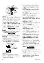
Insert the Switch Pilot Rod (56) into the hole in the Switch
Plate (59). (Refer to Dwg. TPD1819).
1.
2.
3.
4.


