


Page 8 of 8
S237-SA (en)
PN 97999-1860
install two new Oiler Felts (4) in the Oiler Body,
and retain them with the Oiler Adjusting Screw
(5). Run the Screw in until its trailing face is flush
with the face of the Oiler Body.
24. Install the Oiler Body O-rings (3) and (6) in their
respective grooves on the Oiler Body.
25. Install the Oiler Body Assembly in the Backhead
and retain it with the Oiler Body Retainer (7).
26. Place the Housing Seal (17) on the rim of the
Housing.
27. Place the Backhead (1) on the Housing, making
certain the Cylinder Dowel engages the dowel
hole in the Backhead. Install the Backhead Cap
Screws (13) and Lock Washers (12). Tighten them
to 20 ft-lb (27 Nm) torque.
28. Lay the Pump on its side and slide the Impeller
(41), hub side first, on the splined end of the Ro-
tor Shaft. Manually rotate the Impeller. If it rubs
against the Housing, install an Impeller Shim (40)
or Shims as required to provide running clear-
ance between the Impeller and Housing.
29. Install the Impeller Retaining Washer (42) and
Screw (43). Tighten the Impeller Retaining Screw
to 12 to 15 ft-lb (16.2 to 20.3 Nm) torque.
30. For the most efficient operation of the Pump,
particularly against high heads, it is necessary
that the clearance between the Impeller and Im-
peller Cover (45) be regulated at 0.010”. Place the
Impeller Cover on the base of the Housing, using
the required Impeller Cover Shim (44) or Shims to
obtain the desired clearance.
31. Place the Inlet (46) against the Impeller Cover
and install the Impeller Cover Cap Screws (48)
and Lock Washers (47). Tighten the Cap Screws to
9 to 12 ft-lb (12.2 to 16.2 Nm) torque.
32. Inject 10 or 15 strokes of Ingersoll-Rand No. 80
Water Pump Grease into the Grease Fitting (15)
on the Motor Housing (14). Use the No. P25-228
Grease Gun.
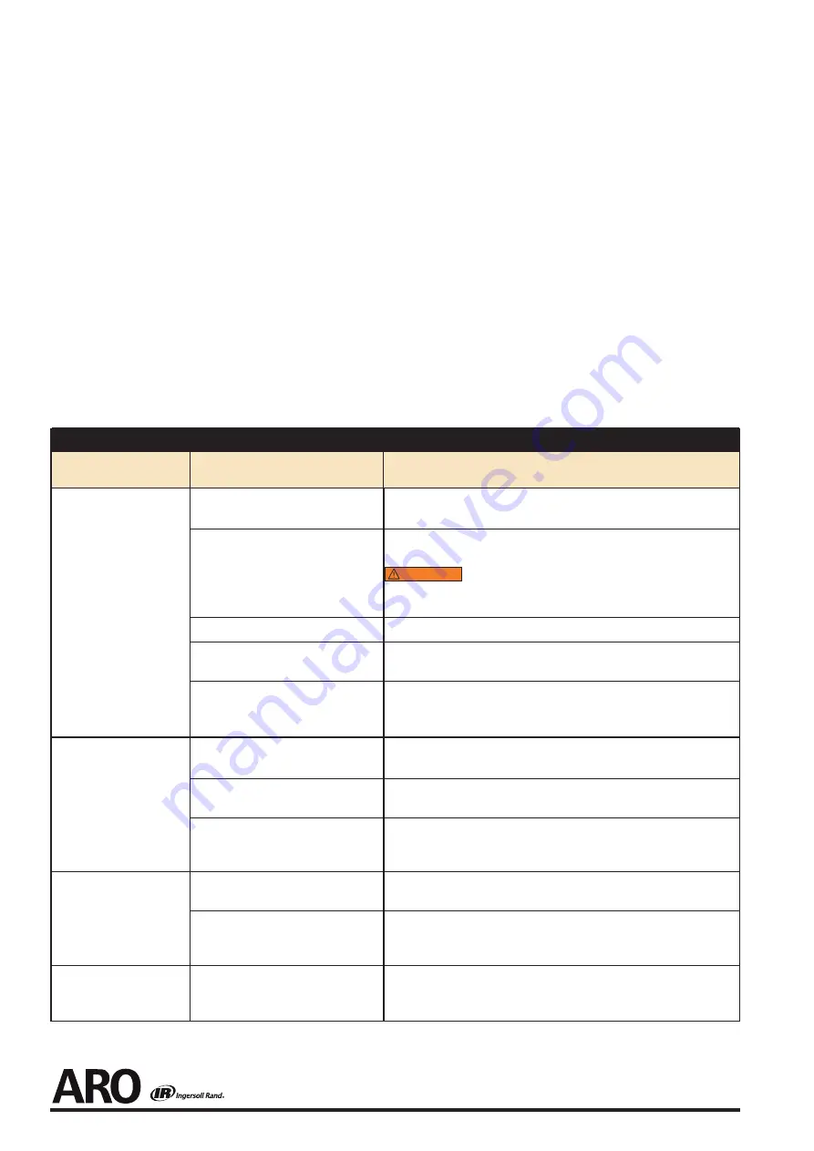
TROUBLESHOOTING GUIDE
Trouble
Probable Cause
Solution
Low power or low free
speed
Low air pressure at the Inlet
Check the air pressure at the Inlet. The pressure must not exceed 90
psig (6.2 bar/620 kPa).
Plugged Inlet Bushing Screen or Air
Strainer Screen
Clean the Screen in a clean, suitable, cleaning solution. If it cannot be
cleaned, replace it.
WARNING
Never operate a Sump Pump without an Inlet Screen.
Ingestion of dirt into the Sump Pump can, in some cases, cause an
unsafe condition.
Worn or broken Vanes
Replace the complete set of Vanes.
Worn or broken Cylinder
Replace the Cylinder if it is worn or broken or if the bore is scored or
wavy.
Improper lubrication or dirt build -up
in the motor.
Lubricate the Sump Pump as instructed in
LUBRICATION.
If lubrica-
tion does not result in satisfactory operation, disassemble the motor
inspect and clean all parts.
Rough operation
Worn or broken Rear Rotor Bearing or
Front Rotor Bearing
Examine each Bearing. Replace the Rear Rotor Bearing Seal Assembly if
worn or damaged or replace the Front Rotor Bearing.
Worn Rotor Key
Replace the Key. Check the Arbor and Rotor for keyslot wear and re-
place if necessary.
Bent Arbor
Mount the Arbor on centers. Check the bearing diameter runout with
an indicator. Replace the Arbor if runout exceeds 0.002” Total Indicator
Reading.
Scoring of End Plates or
Cylinder
Improper assembly
Make certain that all motor parts are properly aligned prior to clamp-
ing the motor assembly.
Rotor Bearing Seal misalignment
Loosen the Cylinder Case Screws. Rotate the spindle by hand to align
the seal. Re-tighten the Screws to 14 ft-lb (19 Nm) torque. The Spindle
must rotate freely.
High free speed
Worn Rotor Bearing Seal
Replace the Rotor Bearing Seal if the outside high diameter of the hub
is worn to 1.76” or smaller and/or the large inside diameter is worn
0.910” or larger.


