Ingersoll-Rand ARO PP10A Series Скачать руководство пользователя страница 6

Page 6 of 12 

PP10A-XXX-XXX-A (en)

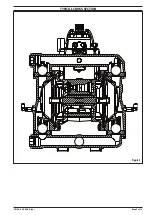
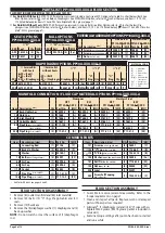
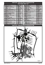
PARTS LIST / PP10A-XXX-XXX-A FLUID SECTION

FLUID SECTION SERVICE KITS (637401-XXX or 637401-XX)


For Fluid Kits With Seats: 

637401

-XXX fluid section service kits include: Seats (see SEAT Option, refer to -XXX in chart below), Balls (see 

BALL Option, refer to -XXX in chart below), Diaphragms (see DIAPHRAGM Option, refer to -XXX in chart below), and items 19, 70, 144, 

175 (listed below) plus items 174 and 94276 Lubriplate

®

 FML-2 grease (page 7).


For Fluid Kits Without Seats: 

637401

-XX fluid section service kits include: Balls (see BALL Option, refer to -XX in chart below), Dia-

phragms (see DIAPHRAGM Option, refer to -XX in chart below), and items 19, 70, 144, 175 (listed below) plus items 174 and 94276 Lubri-

plate® FML-2 grease (page 7).

MATERIAL CODE

[A] 

= Aluminum

[B] 

= Nitrile

[C] 

= Carbon Steel

[Co]  = Copper

[MSp]  = Medical Grade 


    Santoprene

[Sp]  = Santoprene

[SS]  = Stainless Steel

[T] 

= PTFE

COMMON PARTS

Item

Description (size)

Qty Part No.

[Mtl]

1 Connecting Rod

(1) 97146

[C]

5 Back-Up Washer

(2) 95990-3

[A]

9 Washer

(2) 93189-1

[SS]

14 Bolt 

(M12 x 1.75-6g x 25mm)

(2) 95997

[SS]

68 Air Cap

(1) 95994-6

[A]

69 Air Cap

(1) 95994-5

[A]


70 Gasket

(2) 95843

[B]

74 Pipe Plug 

(1/4 - 18 NPT)

(1) Y17-51-N

[C]

126 Pipe Plug 

(1/4 - 18 NPT)

(1) Y17-13-S

[SS]

Item

Description (size)

Qty Part No.

[Mtl]

131 Screw

 (M8 x 1.25  - 6g x 95 mm)

(4) 96001

[C]

144 “U” Cup 

(3/4” x 1-1/8” OD)

(2) Y186-49

[B]

175 “O” Ring 

(5/8” x 13/16” OD)

(2) Y325-114

[B]

180 Washer 

(0.406” ID x 0.031” thick)

(4) 96006

[Co]

181 Roll Pin 

(Ø 0.156 x 0.500)

(4) Y178-52-S

[SS]

195 Nut 

(M8 x 1.25  - 6h)

(4) 96005

[SS]

208 Label

(1) 93007

250 Screw, Self-Tapping 

(1/4” - 14 x 1/2”)

(1) Y334-104-C [C]

SEAT OPTIONS

PP10A-XXX-XXX-A

BALL OPTIONS

PP10A-XXX-XXX-A

“21”

 “22” 

(2-1/2” diameter)

-XXX Seat

Qty [Mtl]

-XXX Ball

Qty [Mtl]

-AXX 96152-A (4) [Sp]

-XAX 93278-A (4) [Sp]

-SXX 96151

(4) [SS]

DIAPHRAGM OPTIONS PP10A-XXX-XXX-A

 Service Kits

with Seats

 Service Kit

without Seats

 “7”

 “19” 

 “33” 

-XXX

-XXX = (Seat)

-XXX = (Ball)

-XXX = (Diaphragm)

-XX = (Ball)

-XX = (Diaphragm) Diaphragm Qty [Mtl]

“O” 

Ring Qty [Mtl]

“O” 

Ring Qty [Mtl]

-XXA 637401-XXA

637401-XA

96267-A

(2) [Sp] 93280 (4) [E] 93279 (4) [E]

-XXM 637401-XXM

637401-XM

96267-M

(2) [MSp] 93282 (4) [T] 93281 (4) [T]

MANIFOLD CONNECTION / FLUID CAP MATERIAL OPTIONS PP10A-XXX-XXX-A

Aluminum

Stainless Steel

NPT

BSP

NPT

BSP

PP10A-AAX-XXX

PP10A-BAX-XXX

PP10A-ASX-XXX

PP10A-BSX-XXX

Item Description 

(size)

Qty Part No.

[Mtl] Part No.

[Mtl] Part No.

[Mtl]

Part No.

[Mtl]

6 Back-Up Washer

(2) 95990-3

[A]

95990-3

[A]

95990-1

[SS]

95990-1

[SS]

15 Fluid Cap

(2) 97684

[A]

97684

[A]

97677

[SS]

97677

[SS]

60 Inlet Manifold

(1) 97686-1

[A]

97686-2

[A]

97679-1

[SS]

97679-2

[SS]

61 Outlet Manifold

(1) 97687-1

[A]

97687-2

[A]

97681-1

[SS]

97681-2

[SS]

63 Pipe Plug 

(1 - 11-1/2 NPT)

(2) Y17-125

[A]

- - - - -

- - -

Y17-55-S

[SS]

- - - - -

- - -

(R1, 1 - 11 BSP)

(2) - - - - -

- - -

96160-2

[A]

- - - - -

- - -

96160-1

[SS]

255 Pipe Plug 

( 1/4"-18 NPT)

(2) Y17-51-S

[A]

Y17-51-S

[A]

Y17-51-S

[SS]

Y17-51-S

[SS]

EXTERNAL HARDWARE OPTIONS PP10A-XXX-XXX-A

Plated Steel

Stainless Steel

PP10A-XXP-XXX-A PP10A-XXS-XXX-A

Item Description 

(size)

Qty Part No. [Mtl] Part No.

[Mtl]

26 Screw 

(M8 x 1.25 - 6g x 30 mm)

(8) 95880-1

[C] 95880

[SS]

27 Screw 

(M8 x 1.25 - 6g x 40 mm)

(20) 95896-1

[C] 95896

[SS]

29 Nut 

(M8 x 1.25 - 6h)

(20) 95879-1

[C] 95879

[SS]

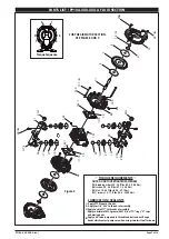
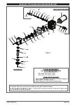
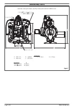
FLUID SECTION DISASSEMBLY

1.  Remove (61) outlet manifold and (60) inlet manifold.

2.  Remove (22) balls, (19) “O” rings (if applicable) and (21) 

seats.

3.  Remove (15) fluid caps. 

4.  Remove the (6) diaphragm washer, (7) diaphragm and (5) 

back-up washer.

NOTE: 

Do not scratch or mar the surface of (1) diaphragm 

rod.

FLUID SECTION ASSEMBLY


y

Assemble in reverse order of disassembly. Refer to the 

torque requirements on page 7.


y

Clean and inspect all parts. Replace worn or damaged 

parts with new parts as required.


y

Lubricate

®


 (1) diaphragm rod and (144) “U” cups with Lu-

briplate FML-2 grease (94276 grease packet is included in 

service kit).


y

Examine torque settings after pump has been re-started 

and run a while.

 

Air Motor Kit parts, see pages 8 and 9.

Содержание ARO PP10A Series

Страница 1: ...ping powders up to 50 lb ft3 Weight PP10X XAX XXX AXXX 28 65 lbs 12 97 kgs PP10X XSX XXX AXXX 46 2 lbs 20 9 kgs Maximum Air Inlet Pressure 50 psig 3 4 bar Maximum Fluidizing Pressure 100 psig 6 9 bar Maximum Particle Size 1 8 dia 3 3 mm MaximumTemperature Limits diaphragm ball seat materials Santoprene 40 to 225 F 40 to 107 C Dimensional Data see page 11 Mounting Dimension 4 x6 25 101 6mmx158 8mm ...

Страница 2: ...ety code requirements OPERATING AND SAFETY PRECAUTIONS READ UNDERSTAND AND FOLLOWTHIS INFORMATIONTO AVOID INJURY AND PROPERTY DAMAGE y y Obtain Material Safety Data Sheets on all materials from the supplier for proper handling instructions WARNING EXPLOSION HAZARD Models containing alu minum wetted parts cannot be used with 1 1 1 trichlo roethane methylene chloride or other halogenated hydrocarbon...

Страница 3: ...el and option chart ARO pumps feature stall resistant design modular air motor fluid sections Air operated double diaphragm pumps utilize a pressure dif ferential in the air chambers to alternately create suction and positive fluid pressure in the fluid chambers valve checks ensure a positive flow of fluid This diaphragm pump was developed to address the unique problems associated with pumping dry...

Страница 4: ...ated which should be available for fast repair and reduction of down time y y Service kits are divided to service two separate dia phragm pump functions 1 AIR SECTION 2 FLUID SEC TION The FLUID SECTION is divided further to match typical part MATERIAL OPTIONS y y Provide a clean work surface to protect sensitive internal moving parts from contamination from dirt and foreign matter during service d...

Страница 5: ...PP10A XXX XXX A en Page 5 of 12 TYPICAL CROSS SECTION Figure 3 ...

Страница 6: ...ice Kits with Seats Service Kit without Seats 7 19 33 XXX XXX Seat XXX Ball XXX Diaphragm XX Ball XX Diaphragm Diaphragm Qty Mtl O Ring Qty Mtl O Ring Qty Mtl XXA 637401 XXA 637401 XA 96267 A 2 Sp 93280 4 E 93279 4 E XXM 637401 XXM 637401 XM 96267 M 2 MSp 93282 4 T 93281 4 T MANIFOLD CONNECTION FLUID CAP MATERIAL OPTIONS PP10A XXX XXX A Aluminum Stainless Steel NPT BSP NPT BSP PP10A AAX XXX PP10A ...

Страница 7: ...0 3 27 1 Nm 131 screws 12 17 ft lbs 16 2 23 04 Nm LUBRICATION SEALANTS Apply PTFE tape to threads Apply Loctite 242 to threads at assembly Apply Loctite 271 to threads at assembly Apply Lubriplate FML 2 grease 94276 to all O rings U cups and mating parts Apply anti seize compound to threads and bolt and nut flange heads which contact pump case when using stainless steel fasteners PARTS LIST PP10A ...

Страница 8: ...asing 111 spool MAJOR VALVE REASSEMBLY 1 Install new 138 and 139 U cups on 111 spool LIPS MUST FACE EACH OTHER 2 Insert 111 spool into 135 valve housing 3 Install 137 O rings on 136 plug and assemble plug to 135 valve housing securing with 105 screws 4 Install 140 valve insert 141 gasket into 135 valve housing NOTE Assemble 140 valve insert with dished side toward 141 valve plate Assemble 141 valv...

Страница 9: ... ARE METRIC 105 screw 40 50 in lbs 4 5 5 6 Nm 134 screw 40 50 in lbs 4 5 5 6 Nm LUBRICATION SEALANTS Apply Lubriplate FML 2 grease to all O rings U cups and mating parts Apply Loctite 271 to threads at assembly Apply Lubricate grease toValve Spool assemblies and Bores A replacement major valve service assembly is available separately which includes the following 637395 8 for models PP10A XXX XXX A...

Страница 10: ...D tube x 1 8 27 NPT 5 59474 56 257 Adapter 1 8 27 PTF 1 94812 258 Button BleedValve 1 8 27 NPTF 1 24130 259 Elbow 5 32 OD tube x 1 8 27 NPT 4 59756 4 260 CheckValve 2 CP10 B 261 Mounting Bracket 1 97704 262 Pipe Plug 1 4 18 NPT x 7 16 2 Y17 51 N 263 ControlValve 1 H254PS 264 Pipe Plug with 0 078 orifice 1 2 14 NPT 1 94977 265 Nipple 1 2 14 NPTF 1 x 1 1 8 1 Y27 4 C 267 Tube 1 4 OD x 20 1 59675 268 ...

Страница 11: ...meters mm C A D F Exhaust Port 3 4 14 NPT Air Inlet 1 2 14 NPTF Outlet Inlet 1 11 1 2 NPTF 1 PP10A ASS AAA A A 1 11 BSP PP10A AAS AAA A A B E DIMENSIONS A 375 21 mm B see below C 101 6 mm D 31 75 mm E 457 53 mm F 293 67 mm Pump Model B PP10A ASS AAA A 410 84 mm PP10A AAS AAA A 410 25 mm Figure 7 DIMENSIONAL DATA ...

Страница 12: ...Page 12 of 12 PP10A XXX XXX A en PN 97999 1822 ...

Отзывы: