InfraTec VBIP-G Скачать руководство пользователя страница 21

 VarioCAM

®

 HD head 

7. Start-up 

User Manual 

© InfraTec GmbH 2016 

19 


Connecting the breakout box 
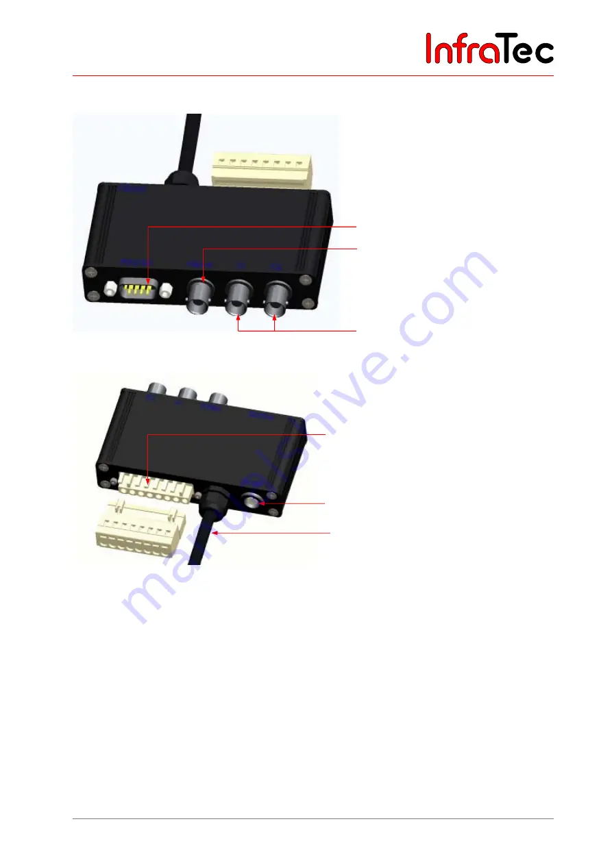


Fig. 14 

Breakout box (RS232, BNC: FBAS, Trigger) 


Fig. 15 

Breakout box reverse 


7.6


Trigger channels VarioCAM

®

 HD head 

7.6.1


Trigger function 

Triggering uses the Ethernet to affect the 16bit IRB data transmission. The trigger signal (5 V) is fed in via 
the BNC sockets of the breakout box identified with T1 and T2 from where it is forwarded to the 
VarioCAM

®

 HD head (right socket) using the connecting cable with 14-pin LEMO connector. 

Commercially available BNC cables can be used in order to connect the trigger signal sources to the 
breakout box. 


T1   

Trigger channel 1 is used by the IRBIS

®

 3 software. 


T2   

Trigger channel 2 is reserved for the SDK and further specific applications. 


BNC video port (PAL/NTSC-FBAS) 

Serial interface (RS232) 

Trigger T1, T2 (configurable) 

LEMO socket, 14-pin for connection to 
the wall plug transformer 

Cable to the VarioCAM

®

 HD head (with  

14-pin LEMO connector) 

Terminal strip (analog output) 

InfraTec

Содержание VBIP-G

Страница 1: ... 01217 Dresden GERMANY Phone 49 351 871 8615 Fax 49 351 871 8727 Email service InfraTec de www InfraTec de InfraTec 2016 All mentioned product names and trademarks remain the property of their respective owners VarioCAM HD head User Manual State March 2016 I n f r a T e c ...

Страница 2: ...I n f r a T e c ...

Страница 3: ...Power over Ethernet PoE 16 7 3 Replacing the lens 17 7 3 1 Bayonet lens interface 17 7 3 2 Screw thread lens interface 17 7 4 Operation using the Ethernet interface IEEE802 3 17 7 5 Operation using breakout box RS232 video output FBAS trigger I O analog out 18 7 6 Trigger channels VarioCAM HD head 19 7 6 1 Trigger function 19 7 6 2 SyncOut 20 8 Software installation 21 8 1 Installation instruction...

Страница 4: ... herein Equipment dependent features are identified accordingly by means of an within this user manual As a matter of principle the descriptions of the technical data and the specific scopes of functions and delivery in the corresponding shipping documents are decisive order confirmation bill of delivery This product is subject to further developments within the scope of technical progress Jenopti...

Страница 5: ...th extraordinary image quality as well as the universal interface concept for digital real time thermography data collection using GigE Vision allow for using the VarioCAM HD head in the most varied fields of application Diverse accessories and different software packages for preprocessing and further processing the recordings turn the VarioCAM HD head into a universal thermography system for a br...

Страница 6: ...camera housing Any intervention performed by other persons is inadmissible and will result in the forfeiture of any warranty claims Only use accessories or spare parts expressly recommended by the manufacturer regarding the VarioCAM HD head Otherwise malfunctions or damages may occur Any warranty claims are excluded for such damages Standards directives The VarioCAM HD head meets the requirements ...

Страница 7: ...r other high radiation sources e g lasers neither during operation nor when switched off because this may result in irrevocable changes to the microbolometer detector the origins of which can be clearly demonstrated The manufacturer does not assume any warranty for damages caused this way It is also absolutely necessary to prevent the sun or other high energy radiation sources from indirectly comi...

Страница 8: ...s are required in order to use these interfaces You will find more information on the aforementioned in the description of the corresponding user manuals 3 2 Description of the functional units Lens The camera lens collects the IR radiation in the field of view emitted by the measuring object and reproduces this IR radiation on the detector array Field of view FOV Field of View and resolution meas...

Страница 9: ...rcuit in an unsupported manner The lens of the thermography system reproduces the thermal radiation from the scene onto these detector elements and these detector elements absorb this radiation The temperature change of the detector elements resulting thereof results in signals that can be analysed electronically read out line by line and column by column using a read out circuit The use of an unc...

Страница 10: ...ds Operation is explained in the manuals of the corresponding software Power supply Optionally an external 15V wall plug transformer accessories or power over Ethernet 48 V IEEE 802 3at standard for a type 1 PD can be used to supply the VarioCAM HD head with power The wall plug transformer is connected to the 14 pin right hand side LEMO socket on the reverse of the housing Interfaces The thermogra...

Страница 11: ...at 640 x 480 Zoom function Up to 32 fold digital A D conversion 16 bit Image storage SDHC card GigE Vision 30Hz and or 60Hz Interfaces DVI D PAL NTSC FBAS GigE Vision RS232 USB2 0 WLAN Bluetooth 2 x digital I O 2 x analogue out process interface Power supply 15 VDC wall plug transformer or PoE wall plug transformer in accordance with IEEE 802 3at standard for type 1 Working temperature range 25 50...

Страница 12: ...n the following are applicable to the VarioCAM HD head with normal lens with a focal distance of 30 mm bayonet interface When using other lenses the total dimensions will change accordingly Fig 1 View from the right side Fig 2 View from the left side Additional fasting thread M5 maximum depth 5 mm 4x I n f r a T e c ...

Страница 13: ... 11 Fig 3 View from the front Fig 4 View from the back Fig 5 View from below Additional fasting thread behind the rubber bumpers 4x M5 maximum depth 5 mm Tripod socket UNC 1 4 20 G maximum depth 6 mm Guide bore Ø 4 5 H10 usable width max 6 mm Rubber pumper I n f r a T e c ...

Страница 14: ...ains the following components Thermography system VarioCAM HD head including lens Protective lens cap User manual VarioCAM HD head Transport box transport packaging Optional accessories Wall plug transformer 15VDC 14 pin LEMO connector PoE wall plug transformer Replacement lenses macro attachments Protective window for lenses laser protection filter Breakout box including connecting cable and 14 p...

Страница 15: ...ower button LEMO socket 14 pin for wall plug transformer FBAS trigger RS232 analog OUT Breakout box Cover for process interface LEMO socket 8 pin for GigE cable Behind cover USB 2 0 DVI D HDMI Red mark for lens installation In order to engage the lens turn clockwise Drilled holes for 90 rotated assembly 4 x M 5 0 Observe the maximum penetration depth of 5 mm 1 4 photo thread connection at camera b...

Страница 16: ...net cable when using PoE power supply 8 pin LEMO connector into the left LEMO socket In order to avoid confusions the Ethernet cable is marked blue Establish the Ethernet connection to the computer Insert the Ethernet cable with the 8 pin LEMO connector red dot pointing to the top into the left LEMO socket Remove the protective cap from the lens Push the Power button and the device is switched on ...

Страница 17: ...ct a motif with a contrast rich scene e g an active electrical device and point the VarioCAM HD head towards this scene Depending on the respective software the focus is set using the corresponding buttons for far near autofocus In IRBIS 3 online the camera remote control window must be opened initially Camera menu Depending on the equipment and the software the thermography images can be saved as...

Страница 18: ...l plug transformer 14 VDC Connect the power supply to the VarioCAM HD head by inserting the power supply cable of the wall plug transformer with its 14 pin LEMO connector red dot pointing to the top into the right LEMO socket on the reverse of the camera Alternatively a modified wall plug transformer is available switching on the camera immediately upon connection e g for starting cameras installe...

Страница 19: ...tive screw thread lens interface the lenses are replaced in analogy to the bayonet The lens is removed by turning it counterclockwise and the lens is attached by turning it clockwise 7 4 Operation using the Ethernet interface IEEE802 3 The following connection options make sure that the VarioCAM HD head can be connected to the PC notebook The accessories described are contained in the scope of del...

Страница 20: ...raphy camera and breakout box must be established For this insert the 14 pin LEMO connector of the breakout box connecting cable into the right LEMO socket on the reverse of the VarioCAM HD head 2 Now the supplied wall plug transformer must be connected to the breakout box The 14 pin LEMO socket required for the aforementioned can be found next to the connecting cable If the VarioCAM HD head is su...

Страница 21: ...here it is forwarded to the VarioCAM HD head right socket using the connecting cable with 14 pin LEMO connector Commercially available BNC cables can be used in order to connect the trigger signal sources to the breakout box T1 Trigger channel 1 is used by the IRBIS 3 software T2 Trigger channel 2 is reserved for the SDK and further specific applications BNC video port PAL NTSC FBAS Serial interfa...

Страница 22: ...esults in the corresponding data being saved The minimum width of a trigger pulse should be 10 µs 7 6 2 SyncOut In order to synchronize other cameras and processes and for active thermography applications the Framesync signal of the VarioCAM HD head can be generated The generation of the Framesync signal is activated by the corresponding software command Framesync low high edge indicates the proce...

Страница 23: ...n order to actuate the VarioCAM HD head Depending on the used Ethernet adapter different configuration options will be available after the Ethernet adapter is installed We recommend using the internal GigE network card at all times for camera connection For the installation described below you must dispose of the access rights of the user group Administrators 8 2 Installation of WinPcap Upon execu...

Страница 24: ...VarioCAM HD head 8 Software installation 22 InfraTec GmbH 2016 User Manual Fig 17 Start of the installation Fig 18 Confirmation of the terms and conditions of the license agreement I n f r a T e c ...

Страница 25: ...ead 8 Software installation User Manual InfraTec GmbH 2016 23 Fig 19 Define automatic start of WinPcap Fig 20 Completion of the installation The installation is finished by clicking the Finish button I n f r a T e c ...

Страница 26: ...Setting the IP address Before configuring the network card for being used in connection with the camera the properties of the interface card to be used must be checked In this releasing non essential functionalities and assigning a fixed IP address are important The screenshots shown below provide an overview Fig 22 Properties of the LAN connection Please note that you only need the components des...

Страница 27: ... following IP address menu item During the further progress of the installation you will need two free network addresses Should you have any questions regarding this please contact your network administrator directly The Retrieve IP address automatically option must not be selected If this option is however activated the computer will try to retrieve a dynamic network address from the camera syste...

Страница 28: ...y in order to achieve a trouble free Ethernet connection to the VarioCAM HD head This function significantly reduces the occupancy rate of the network and allows for loss free data transmission even at high frame rates Fig 24 Setting Jumbo Packet Fig 25 Speed and duplex mode Please select the highest possible value from the available drop down list Please preferentially select the value 1 0 Gbit s...

Страница 29: ...software User Manual InfraTec GmbH 2016 27 9 Establishing a connection to the IRBIS 3 software Within the IRBIS 3 program the Connect button must be clicked in the Camera menu item in order to establish the connection between camera and software I n f r a T e c ...

Страница 30: ...VarioCAM HD head 9 Establishing a connection to the IRBIS 3 software 28 InfraTec GmbH 2016 User Manual I n f r a T e c ...

Страница 31: ... The following Select camera dialog must be used to select the camera type VarioCAM HD Clicking the Accept button will start the establishment of the connection to the thermography system Fig 27 IRBIS 3 Select camera All further functions of the program are described in detail in the manuals RBIS 3 Infrared thermography software I n f r a T e c ...

Страница 32: ...ut applying pressure After wiping both the cloth and the surface of the lens should be nearly dry meaning that no smearing or smudges should remain For strongly adhering dirt or fingerprints if necessary a gentle uniform pressure may be applied For such instances surgical cotton or cotton swabs may be suitable for use in addition to the types of cloths listed above These can be moistened with a fe...

Страница 33: ...circuit boards These components must be disposed of specifically when the device is at the end of its use The manufacturer offers to take back the VarioCAM HD head product from the customer in order to ensure that the device is disposed of in an environmentally friendly manner when the device is at the end of its use In this case please return the device to the address mentioned in chapter 12 Serv...

Страница 34: ...uarantees the implementation of the service on the VarioCAM HD head product Should you experience any failures or require the performance of technical maintenance works please contact your dealer or customer services using the following address InfraTec GmbH Infrarotsensorik und Messtechnik Gostritzer Straße 61 63 01217 Dresden GERMANY Phone 49 351 871 8615 Fax 49 351 871 8727 Email service InfraT...

Отзывы: