


M2M Control CX320 Technical Manual V1.01
Page 31 of 42
Switches
DIP-switch
The M2M Control CX320 unit contains four dip-switches, and three of them are available for the
application to use (the
fourth dip-switch is reserved for future use
).
The dip-switches are located on the top side of the unit for easy user access (see the graphical
overview).
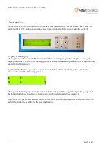
System switch (RST)
The M2M Control CX320 device contains a combined reset/diagnostic switch. This switch is accessible
from the front of the unit (see the graphical overview). It is necessary to use a small thin object with a
diameter of approx. 2 mm, for example, a straightened-out paper clip for this purpose.
By activating the switch shortly, the CX320 device will perform a full reset.
If the reset switch is held down for approx. 3 seconds
1
, the device will instead enter recovery mode
2
,
and the application will not be started. The system will automatically turn on the cellular engine in
recovery mode to connect to the network and M2M Control Communication Hub (formerly: M2M
Control GPRS Gateway) - if configured.
Pressing reset will also activate the device when in power-down mode. If external power is removed
and the backup battery is disabled, the reset switch can still be used to boot into recovery mode, as
long as there is enough power left on the battery.
1 System LED S2 will flash green three times when this state is entered.
2 System LED S1 will indicates this state by fast blinking green or yellow.


