INFOSEC UPS SYSTEM
- 4, rue de la Rigotière - 44700 Orvault - France - www.infosec.fr
Hot Line :
tél : +33(0)2 40 76 15 82 -
fax :
+33 (0)2 40 94 29 51- [email protected] - 10 05 04 205 02
-
5
-
5 OVERVIEW
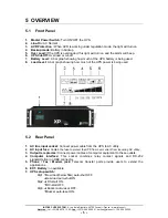
5.1 Front
Panel
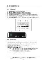
1. Master Power Switch:
Turn ON/OFF the UPS.
2. Line-On:
AC Normal .
3. AVR Protection :
When AVR is working under regulation mode, the light will turn on.
4. Backup mode:
Battery in backup
5. Over Load:
If the UPS is overloaded, this light will turn on and the alarm will beep.
6. UPS Cut-Off:
Overload or cut-off
7. Battery Level:
A bar graph showing how much of the UPS battery is being used.
8. Load Level:
A bar graph showing how much of the UPS power is being used.
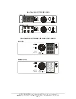
5.2 Rear
Panel
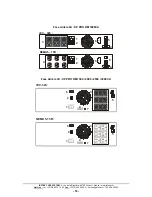
1. AC line input socket:
Connect power cable from the UPS to AC utility.
2.
AC input fuse:
Contain the fuse to protect the UPS from over current from incoming AC utility.
3. Output receptacles:
Connect power cables of computer equipment to these outlets.
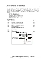
4. Computer interface:
This socket combines relay contact signals and RS-232
signals(Option) on DB9 connector.
5. Phone / Fax / Modem jack:
Telecom transfer ports provide users to extend the
applications.
6. EXT. Battery:
no available
7. UPS setup switch:
Dip1.
Low load(below 50w) auto-shut OFF.
Low load auto-shut ON.
Dip2.
DC-start ON.
DC-start OFF.
Dip3.
Buzzer auto-reset OFF.
Buzzer auto-reset ON.
1


