Infinova V3060 Series Скачать руководство пользователя страница 16


10 

the following situations and parallelism of pins. 


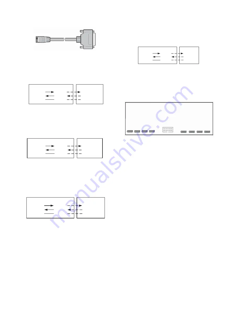
Figure 2-14 Serial port connection cable 


(1)


When the RJ45 serial port of the DVR is connected with the 
device with DB25 female type connector, the pin parallelism 
as follows: 

RJ45

TXD 4
RXD 5

GND 2/7

DB25(Male)

3 TXD 
2 RXD

7 GND

DB25(Female)

3 RXD 
2 TXD
7 GND

Serial Port Connection Cable

DB25 Female 

Type Device


Figure 2-15 RJ45 and DB25 female type device connection 

 
(2)


When the RJ45 serial port of the DVR is connected with the 
device with DB25 male type connector, the pin parallelism as 
follows: 

RJ45

TXD 4

RXD 5

GND 2/7

DB25(Female)

2 TXD
3 RXD 

7 GND

DB25(Male)

2 RXD 
3 TXD
7 GND

Serial Port Connection Cable

DB25 Male 

Type Device


Figure 2-16 RJ45 and DB25 male type device connection 


(3)


When the RJ45 serial port of the DVR is connected with the 
device with DB9 female type connector, the pin parallelism as 
follows:


RJ45

TXD 4

RXD 5

GND 2/7

DB9(Male)

3 TXD 

2 RXD
5 GND

DB9(Female)

3 RXD 
2 TXD

5 GND

Serial Port Connection Cable

DB9 Female 

Type Device


Figure 2-17 RJ45 and DB9 female type device connection 


(4)


When the RJ45 serial port of the DVR is connected with the 
device with DB9 male type connector, the pin parallelism as 
follows:


RJ45

TXD 4
RXD 5

GND 2/7

DB9(Female)

2 TXD
3 RXD 

5 GND

DB9(Male)

2 RXD 
3 TXD
5 GND

Serial Port Connection Cable

DB9 Male Type 

Device


Figure 2-18 RJ45 and DB9 male type device connection 


Note:

 Refer to 

Section 5.3 Serial Port Settings

 for the connection of 

DVR and serial port devices (i.e. matrix). 


2.7 Install Writer 


Figure 2-19 Writer drive installation diagram 


The steps to install writer as follows: 
(1)


Power off the DVR, open the housing, disassemble the hard 
disk mounting rack and open the writer door; 

(2)


Place the writer on the rack, and fix with screws; 

(3)


Connect the data cable; 

Note

: For V3060W series DVR, 5 SATA ports (No.4-8 port) are 

available. No.4 port is writer interface. No.5-8 ports are hard disk 
interface. No.1-3 is reserved. 
(4)


Connect the power supply cable; 

(5)


Assemble the hard disk mounting rack; 

(6)


Close and fix the housing with screws. 

Note

: Make sure the writer door is open when writer is in using. 


Содержание V3060 Series

Страница 1: ...d Network Digital Video Recorders V3060 series DVR employs high performance power PC hardware structure embedded Linux system and 1000M network port design to provide an excellent digital product for...

Страница 2: ...o Recorders all comply with Part 15 of the FCC rules Operation is subject to the following two conditions y This device may not cause harmful interference y This device must accept any interference re...

Страница 3: ...away from ground and access way z Refer all service matters to qualified personnel z Save product packaging to ensure availability of proper shipping containers for future transportation Indicates tha...

Страница 4: ...metal on DVR which may cause short circuit even fire inside DVR z Install the harddisk correctly before use or else you can t make any record operation z The dust of the mainboard may cause short cir...

Страница 5: ...DVR 14 4 2 User Login and Authority 14 4 2 1 User Login 14 4 2 2 User Authority 15 4 3 Preview 15 4 3 1 Switch Preview Modes 15 4 3 2 Preview Setting 15 4 4 PTZ Control 15 4 4 1 PTZ Parameters Setting...

Страница 6: ......

Страница 7: ...ntrol protocols of leading encoder support preset and pattern y Support zoom in function by mouse operation when control Infinova second generation dome y 8 SATA hard disks supported y Hard disk stand...

Страница 8: ...indicator Orange flickering transmitting receiving data 3 STATUS Status indicator Green DVR is being controlled by remote controller Red DVR is in PTZ control status Orange DVR is in PTZ control stat...

Страница 9: ...out in PTZ Control 2 Switch among tabs in submenu 3 Hide Display lower status bar in preview interface TELE Control key Zoom in in PTZ control PTZ Control key 1 Quick enter to PTZ control mode 2 Close...

Страница 10: ...s numeral English and symbol 2 Set the full screen as setting area in Mask Video mask alarm Motion detection setting 6 SYS System Information Function key The function is the same with SYS key in fron...

Страница 11: ...top using remote controller Press DEV key when the DVR is being controlled the status indicator will turn off and then the remote controller stops to control the DVR 4 Shutdown DVR via remote controll...

Страница 12: ...o video recording parameters 2 Installation Tool One Philips head screw driver 3 Install Hard Disk 1 Open the housing 2 Install the hard disk 8 interfaces are available for V3060 DVR 3 Remove the hard...

Страница 13: ...utput and menu display and OUT2 only for video signal output 6 AUDIO OUT Standard BNC connector for 1 ch audio output 7 AUDIO IN 16 ch audio inputs 2 standard DB15 ports with 2 DB15 to BNC connection...

Страница 14: ...C Load Indicator J1400 1 G 5V Alarm Circuit Figure 2 5 Alarm output DC load connection DVR Alarm Output Port AC or DC Load J1400 1 G 5V Relay DC AC Figure 2 6 Alarm output relay connection As shown in...

Страница 15: ...twisted cable 8 cores one standard RJ45 connector one or more DB25 or DB9 plug a special tool for RJ45 one soldering iron and some solder 2 Pin definition Refer to Figure2 7 for the pin sequence of R...

Страница 16: ...GND Serial Port Connection Cable DB9 Female Type Device Figure 2 17 RJ45 and DB9 female type device connection 4 When the RJ45 serial port of the DVR is connected with the device with DB9 male type co...

Страница 17: ...3 3 Every menu has many operations below section will have detailed introduction on operation of common use control and input method 3 1 1 Cursor Switching The cursor can be switched via WIDE and key...

Страница 18: ...menu Unselect All Cancel the selection of the options in current menu Search Search the content match with the setting Refresh list Refresh the data in the list Play Play the file selected in the curr...

Страница 19: ...tings Video Mask Alarm Output Audible Warning Control Center Alarm Preview and 4 Alarm Outputs Sensitivity Area Schedule Week Time Video Motion Detection Linkage Recording PTZ control Audible Warning...

Страница 20: ...de Mode Default Reboot Shutdown Chapter 4 Main Functions Introduction 4 1 Turn on DVR Note The DVR supports 100V 240VAC self adaptive power supply Before powering on please confirm the AC voltage matc...

Страница 21: ...arts follows 1 Preview 2 Manual recording press REC key to turn on the recording status list 3 Playback press PLAY key to turn on play interface 4 PTZ control press PTZ key to start the PTZ control Fr...

Страница 22: ...status press PTZ key to enter PTZ control status There will be a login window if the operation password is enabled Login with the user name that has the authority to perform PTZ control and correct pa...

Страница 23: ...T key to call out the drop down list to select the desired channel and press ENT key to confirm the selection Select the video mask option and press ENT key to enable it and allow mask alarm setting s...

Страница 24: ...NT key 3 Set schedule Refer to 3 Set schedule of Video mask alarm in section 4 5 1 4 Set alarm output Refer to 4 Set alarm output of Video mask alarm in section 4 5 1 5 Copy and save Refer to 5 Save o...

Страница 25: ...e s alarm input 4 5 3 Abnormity Alarm Abnormity alarm includes hard disk full hard disk error network cable disconnected reserved unauthorized access and network conflict alarms Users can response qui...

Страница 26: ...T key to cancel the selection to stop the manual recording Note 1 For manual recording it must stop manually or the DVR will keep on recording Since the priority of alarm recording is higher the manua...

Страница 27: ...m of compression the video if set the bit rate type to variable rate Normally the max bit rate and resolution are direction ratio the higher resolution requires higher max bit rate vice versa The max...

Страница 28: ...1 8 and 1 16 and 4 fast play speeds X2 X4 X8 and X16 3 Functional button instruction Button Instruction Button Instruction Button Instruction Pause Play Stop Rewind 30s Forward 30s Slow motion playba...

Страница 29: ...er off 1 Turn off DVR through Menu Enter System Menu and select Shutdown as shown in Figure 4 18 Figure 4 18 Press ENT key a prompt box Are you sure to shut down now will appear as shown in Figure 4 1...

Страница 30: ...tch time It has 8 options never 5s 10s 20s 30s 1m 2m and 5m The operation is the same with monitor 4 Alarm preview It has two options On and Off the operation is the same with monitor 5 Alarm preview...

Страница 31: ...utomatically when enable this option 10 DNS server The operation is the same with IP address Advanced settings The advanced settings include 6 options as follows y HTTP port y SNMP port y Alarm center...

Страница 32: ...system with administrator and select the user The privileges of the selected user will display at the bottom side of the interface Move the cursor to select the privilege needs to be added or cancell...

Страница 33: ...u and 5 different levels are available The default level is opaque 6 Output to Two options BNC and VGA The main output of the DVR will change to the set output after the device reboot 7 VGA resolution...

Страница 34: ...A B C D four disks A disk is the first disk and if there re C D disk only C disk is the first disk The previous log will lose if replace the first disk It s recommended to assign one disk as the first...

Страница 35: ...change the U disk pull out the old one and plug a new one and then click Refresh If the disk is still unidentifiable choose formatting to continue If the problem remains unsolved there might be an inc...

Страница 36: ...utdown If choose Cancel and press ENT key The prompt will close and the system will not reboot or shutdown 5 5 7 General Channel Settings Figure 5 19 While the screen shows the main interface press ME...

Страница 37: ...crophone in the list of Show the following volume controls as shown in the following figure Figure 5 23 5 Click OK to return the recording dialog box shown in the following figure Figure 5 24 6 Adjust...

Страница 38: ...Infinova 51 Stouts Lane Monmouth Junction NJ 08852 U S A Tel 1 888 685 2002 USA only 1 732 355 9100 Fax 1 732 355 9101 sales infinova com V1 1 1312...

Отзывы: