background image

User Manual

5-3

V1.0 

TriBoard TC3X6 TH V1.0 and TriBoard TC3X6 V1.0

 2019-09

TriBoard Manual TC3X6

Hardware: TriBoard TC3X6 TH V1.0 and TriBoard TC3X6 V1.0


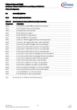
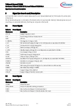
Signal (on board used) Description

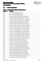
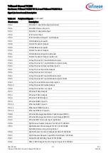
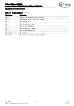
 P15.2

ASCLIN0 Transmit Output (optional)

 P15.1

ASCLIN1 Receive Input A

 P15.0

ASCLIN1 Transmit Output

 P15.4

I2C0 Serial Clock

 P15.5

I2C0 Serial Data Input C und Output

 P20.7

CAN00 Receive Input B

 P20.8

CAN00 Transmit Output

 P00.5

CAN11 Receive Input B

 P00.4

CAN11 Transmit Output

 P00.1

CAN10 Receive Input A (optional)

 P00.0

CAN10 Transmit Output (optional)

 P02.0

E-Ray Channel A Transmit Data Output

 P02.4

E-Ray Channel A Transmit Data Output enable

 P02.1

E-Ray Channel A Receive Data Input 2

 P10.1

E-Ray Channel A Enable Output

 P10.2

E-Ray Channel A Error Input

 P02.2

E-Ray Channel B Transmit Data Output

 P02.5

E-Ray Channel B Transmit Data Output enable

 P02.3

E-Ray Channel B Receive Data Input 2

 P20.10

E-Ray Channel B Enable Output

 P20.9

E-Ray Channel B Error Input

 P11.2

Ethernet TXD1 Output

 P11.3

Ethernet TXD0 Output

 P11.6

Ethernet TXEN Output

 P11.9

Ethernet RXD1 Input A

 P11.10

Ethernet RXD0 Input A

 P11.11

Ethernet CRSDV Input A

 P11.12

Ethernet REFCLK Input A

 P02.8

Ethernet Management Data Clock Output (MDC)

 P00.0

Ethernet Management Data Input/Output (MDIO)

 P10.3

Ethernet MD Interrupt Input (optional)

 P14.6

QSPI2 Slave Select Output 2 for SCS of TLF35584

 P15.3

QSPI2 Master Clock Output for SCL of TLF35584
ASCLIN0 Receive Input B (optional)

 P15.6

QSPI2 Master Transmit Output for SDI of TLF35584

 P15.7

QSPI2 Master Receive Input B for SDO from TLF35584

 P02.7

Output for Watchdog Input of TLF35584

 P33.8

SMU_FSP0 Output for Error Signal Input of TLF35584

Table 5-6

Peripheral Signals (continued)

 Short name

Description

Содержание TriBoard TC3 6 Series

Страница 1: ...ist different hardware with Through Hole socket TriBoard TC3X6 TH and soldered devices TriBoard TC3X6 The schematic is identically for the all boards if not other mentioned in chapter schematic The placing on the boards is slightly different on bottom side around the TC3X6 itself dependent of the space socket need more space and has through hole but the most components are on the same location onl...

Страница 2: ...ctor 3 5 3 6 1 Serial Connection to PC 3 6 3 6 2 miniWiggler JDS 3 6 3 7 FlexRay E RAY 3 7 3 8 Serial Eeprom 3 7 3 9 MultiCAN 3 7 3 10 LIN 3 7 3 11 Ethernet 3 8 3 12 HSCT optional 3 8 3 12 1 High speed with HSCT 3 9 3 13 ADC 3 9 3 14 Other peripherals 3 11 3 15 Toggle LED s 3 11 3 16 Buttons 3 11 3 17 Debug System 3 11 3 17 1 OCDS1 3 11 3 17 2 DAP 3 11 3 17 3 DAP_SCR 3 11 3 17 4 High speed with DA...

Страница 3: ...iew 6 2 6 3 TC336 Connector Top View 6 4 6 4 Power connector pinout 6 6 6 5 USB connector pinout 6 6 6 6 FlexRay ERAY connector pinout 6 6 6 7 CAN connector pinout 6 6 6 8 LIN connector pinout 6 7 6 9 HSCT connector pinout 6 7 6 10 Ethernet connector pinout 6 7 6 11 OCDS1 connector pinout 6 8 6 12 DAP connector pinout 6 8 6 13 ETK connector pinout 6 9 6 14 Ethernet miniWiggler power connector pino...

Страница 4: ...ped with a variety of memories and peripherals for connection to the environment There is also an interface for the On Chip Debugging Features OCDS1 and DAP The Evaluation Board allows easily the development of TriCore applications with the corresponding tools Subsequently the applications can be downloaded and can be tested with the powerful debugger software This TriBoard Hardware Manual familia...

Страница 5: ...x 10 pin header for DAP and DAP_SCR 10pin 2x5 Header for LIN Transceiver LIN 2 x 10pin 2x5 Header for CAN High Speed Transceiver CAN0 and CAN1 2 x 10pin 2x5 Header for FlexRay ERAY A and ERAY B four 80 pin connectors male four 80 pin connectors female with all I O signals optional ETK connector optional 6pin IEEE1394 Socket for HSCT Components Infineon s Multi Voltage Safety Micro Processor Supply...

Страница 6: ...stems functionality 2 2 Block Diagram Figure 2 1 TriBoard Block Schematic 2 EUI 48 is trademarked by IEEE Micro USB miniWiggler OCDS1 USB XTAL FlexRay Transceiver Transceiver TxCAN0 TxCAN1 RxCAN0 RxCAN1 TC3X6 e g TC366 TC336 TriCore CPU PLL CAN0 CAN1 ERAY B ERAY A TX0 RX0 8 LED s P33 4 up to P33 7 P20 11 up to P20 14 Serial EEPROM with EUI 48 RMII PHY Twisted Pair RJ45 LIN LIN Transceiver TX1 RX1 ...

Страница 7: ...C3X6 V1 0 Features 2 3 Placement Figure 2 2 TriBoard TC3X6 TH V1 0 Placement U401 U 307 X406 Y301 X306 X201 U502 U501 L502 L501 C502 C501 R501 X603 D508 S502 Y401 BU 401 S201 X305 X304 X303 C303 D401 D402 T301 T302 X301 X302 X601 D302 D303 D304 D305 D306 D307 D 308 D309 D505 D506 D507 D504 X401 X501 S501 X604 X602 X404 U201 S202 X402 Y201 X502 ...

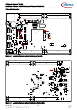
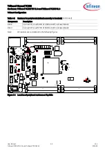
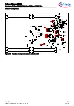
Страница 8: ...6 will not work If you get the board with TC336 and you will use the board with TC366 then you must remove R541 R542 and C518 and assemble R528 R529 and R523 with a resistor 0R size 0603 The mentioned components are red marked in the following Figure 3 1 Figure 3 1 Location of PMS PMSLE components on bottom side R 541 R542 R388 R381 R380 R378 Q301 R368 R382 R369 C320 C 317 R389 R383 R385 R370 C B3...

Страница 9: ...ill not work ERAY can t be used CAN1 can t be used Communication with TLF35584 not possible different pinning therefore following signals are different connected Board signal name TC356 signal name TC336DA signal name P00 0 P10 3 P10 3 P00 1 P02 1 P02 1 P00 2 P10 2 P10 2 P00 3 P50 7 P50 7 P00 4 P50 6 P50 6 P00 5 P10 7 P10 7 P00 6 P10 8 P10 8 P00 7 P50 9 P50 9 P00 8 P50 8 P50 8 P00 9 P50 11 P50 11 ...

Страница 10: ...P11 9 P11 9 P13 0 P11 0 P11 0 P13 1 P11 1 P11 1 P13 2 P12 1 P12 1 P13 3 P11 14 P11 14 P14 8 P11 13 P11 13 P14 10 P12 0 P12 0 P15 7 NC NC P15 8 NC NC P22 0 NC NC P22 1 NC NC P22 2 NC NC P22 3 NC NC P23 3 NC NC AN0 NC NC AN4 AN0 AN0 AN5 NC AN4 AN6 NC AN5 AN7 AN10 AN10 AN9 NC AN13 AN10 AN12 AN12 AN12 NC AN21 AN13 NC AN14 AN14 NC AN9 AN15 NC AN15 AN16 P02 3 P02 3 AN17 P00 0 P00 0 AN24 P02 8 P02 8 AN25...

Страница 11: ...he reset button The Board has to be connected to a 3 5V to 40V DC power supply The power consumption is not specified yet but a supply with 12V and 500mA is recommended The pinout for the supply connector is shown in Figure 6 5 There can be used any standard power pack with a connector where the positive line is surrounded by the ground line 3 3 1 Failsafe handling In case that the device don t co...

Страница 12: ... as serial connection via USB and Debugging via DAS For the pinout of USB socket see Figure 6 6 NOTE Before connecting the board to the PC make sure that the actual DAS software is installed on the PC For actual DAS software please contact your local FAE The software can also be found on DAS website R379 R372 C305 C310 CB313 CB314 CB315 C311 U307 Y301 R375 R376 CB316 CB317 U308 C516 X306 X201 U502...

Страница 13: ...t of DAS If you have connected the board to the PC and there runs the DAS server then a working connection is visible via the green ACTIV LED The status RUN LED is switched on off through the DAS Server depending on the used debugger client IMPORTANT Make sure that there is no or a tristated connection on X401 OCDS1 and X402 DAP if the ACTIV LED is on R 541 R542 R388 R381 R380 R378 Q301 R368 R382 ...

Страница 14: ...address of this EEPROM is 0x50 The upper half of the array 80h FFh is permanently write protected Write operations to this address range are inhibited Read operations are not affected This upper half contains a pre programmed EUI 48 node address which can be used as MAC ID for Ethernet The other 128 bytes are writable by customer To disconnect disable the EEPROM remove resistor R348 and R349 3 9 M...

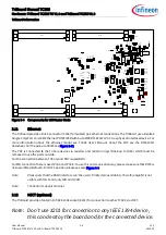
Страница 15: ...oard provide a footprint of IEEE 1394 socket X201 for connection to other TC3XX via HSCT Note Don t use X201 for connection to any IEEE 1394 device this can destroy the board and or the connected device R 541 R542 R388 R381 R380 R378 Q301 R368 R382 R369 C320 C 317 R389 R383 R385 R370 C B31 1 CB312 R 386 C306 C205 CB204 C203 C204 C207 C208 R523 Q506 L503 C 520 C521 R252 R250 R251 R253 R254 R529 R52...

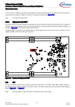
Страница 16: ... in the following figures Figure 3 6 and Figure 3 7 Note AN24 adn AN25 are not connected on TC336 and therefore not usable R 541 R542 R388 R381 R380 R378 Q301 R368 R382 R369 C320 C 317 R389 R383 R385 R370 C B31 1 CB312 R 386 C306 C205 CB204 C203 C204 C207 C208 R523 Q506 L503 C 520 C521 R252 R250 R251 R253 R254 R529 R528 R 525 R371 R367 R365 R314 R313 R238 R 534 R511 R512 R505 R504 C510 R 502 R506 ...

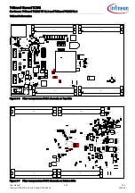
Страница 17: ...401 X501 S501 R354 R452 R213 C B201 R398 R 255 R256 R390 R348 R349 X502 X604 R346 R347 X602 X404 U201 S202 R 541 R542 R388 R381 R380 R378 Q301 R368 R382 R369 C320 C 317 R389 R383 R385 R370 C B31 1 CB312 R 386 C306 C205 CB204 C203 C204 C207 C208 R523 Q506 L503 C 520 C521 R252 R250 R251 R253 R254 R529 R528 R 525 R371 R367 R365 R314 R313 R238 R 534 R511 R512 R505 R504 C510 R 502 R506 Q505 Q501 D501 C...

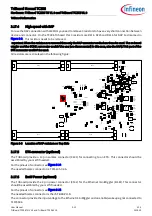
Страница 18: ...lable e g wakeup the TLF35584 via P33 10 3 17 Debug System 3 17 1 OCDS1 The OCDS1 signals are connected to the IDC16 plug X401 They work with the port supply of Microcontroller 5V default or 3 3V For pinout of the connector see Figure 6 12 You can connect any debugger to this connector The signals BRKIN and BRKOUT are not connected per default If you need this signals in the connector then assembl...

Страница 19: ...by your self if needed For the pinout of connector see Figure 6 15 The needed Samtec connector is the JST B4B PH K The connector provide the input voltage to the Ethernet miniWiggler and an enable wakeup signal connected to TLF35584 R 541 R542 R388 R381 R380 R378 Q301 R368 R382 R369 C320 C 317 R389 R383 R385 R370 C B31 1 CB312 R 386 C306 C205 CB204 C203 C204 C207 C208 R523 Q506 L503 C 520 C521 R25...

Страница 20: ...09 TriBoard Manual TC3X6 Hardware TriBoard TC3X6 TH V1 0 and TriBoard TC3X6 V1 0 TriBoard Information Because the device don t have a VDDSB pin the 1 25V standby supply pin of the connector is not connected to the device only to pin 75 of connector X602 and X702 on this board ...

Страница 21: ...e Dipswitch 1 you must make a power cycle switch off switch on to use the new configuration In case that TriState is selected Dipswitch 1 is set to ON then the I O pins are floating If you need a specific level on different pins during startup e g driver pins then you must add the needed pull device up or down Some pins especially the HWCFG pins haven always the needed external pull up and or pull...

Страница 22: ...to toggle LEDs D302 D305 assembled R399 Connect V_UC to toggle LEDs D306 D309 assembled R423 Connect P20 0 with miniWiggler JDS not assembled R424 Connect P20 0 with OCDS1 connector not assembled R425 Connect P21 7 with OCDS1 connector not assembled R426 Connect P20 2 with OCDS1 connector not assembled R427 Connect P21 7 with USR1 of miniWiggler JDS not assembled R428 Connect P20 2 with USR1 of mi...

Страница 23: ...504 X401 X501 S501 R354 R452 R213 C B201 R398 R 255 R256 R390 R348 R349 X502 X604 R346 R347 X602 X404 U201 S202 R 541 R542 R388 R381 R380 R378 Q301 R368 R382 R369 C320 C 317 R389 R383 R385 R370 C B31 1 CB312 R 386 C306 C205 CB204 C203 C204 C207 C208 R523 Q506 L503 C 520 C521 R252 R250 R251 R253 R254 R529 R528 R 525 R371 R367 R365 R314 R313 R238 R 534 R511 R512 R505 R504 C510 R 502 R506 Q505 Q501 D...

Страница 24: ...sembled R323 Connect P10 1 with EN of ERAY A transceiver assembled R324 Connect P10 2 with ERRN of ERAY A transceiver assembled R340 Connect P02 2 with TXD of ERAY B transceiver assembled R341 Connect P02 5 with TXDEN of ERAY B transceiver assembled R342 Connect P02 3 with RXD of ERAY B transceiver assembled R343 Connect P20 10 with EN of ERAY B transceiver assembled R344 Connect P20 9 with ERRN o...

Страница 25: ... U502 C505 U501 L502 L501 CB501 C502 C507 C 509 C 508 C501 C503 C504 R501 R507 R 508 R509 CB502 X603 D508 S502 R402 R403 CB408 Y401 U401 CB401 R401 L401 BU 401 C402 CB405 X406 R457 R 249 R248 R246 R245 R244 X402 S201 R377 CB202 R204 R205 X305 X304 X303 R236 R234 R232 R230 R361 R359 R212 D301 C303 U408 U407 U406 R451 R 455 R456 R454 R446 R444 CB419 CB418 CB417 CB416 CB415 CB414 D401 R430 R429 R423 ...

Страница 26: ...7 R438 CB404 R405 R440 CB409 R416 R418 R 419 R414 R420 C406 Q402 Q403 C404 C405 CB410 CB411 CB412 R441 R442 C40 1 R404 C403 CB413 L402 U405 R433 C518 R 431 R208 R408 R 215 R214 U306 R521 R240 R364 R363 R362 R3 60 R211 CB310 C304 R449 R 448 R447 R445 R443 R413 D403 R450 R422 R421 U403 Q401 R412 R415 R410 R 409 CB407 R407 U402 R406 CB406 R305 R306 R308 R309 R 315 R316 R318 R319 R301 R311 R341 R340 R...

Страница 27: ...re Regulator Voltage 5 8V V_UC Microcontroller Supply Voltage 5V or 3 3V depends on assembled TLF35584 V_CO Communication Supply Voltage 5V V_VR Reference Supply Voltage 5V V_STBY Standby Supply Voltage 5V or 3 3V depends on assembled TLF35584 VDD Core Supply Voltage 1 25V VDDP3 Flash Power Supply Voltage 3 3V VFLEX Flexport Supply Voltage 3 3V VEXTOSC Oscillator Port Supply Voltage 5V or 3 3V dep...

Страница 28: ...ble 5 4 Clock Signals Short name Description XTAL1 Crystal Oscillator Input XTAL2 Crystal Oscillator Output Table 5 5 Debug Signals Short name Description TRST Test Reset DAP0 Device Access Port Line 0 Test Data Clock TCK DAP1 Device Access Port Line 1 Test Data Select TMS DAP2 Device Access Port Line 2 Test Data Output TDO P21 6 Test Data Input TDI DAP0_A DAP0 TCK from debug connectors DAP1_A DAP...
Страница 29: ... Ray Channel B Transmit Data Output P02 5 E Ray Channel B Transmit Data Output enable P02 3 E Ray Channel B Receive Data Input 2 P20 10 E Ray Channel B Enable Output P20 9 E Ray Channel B Error Input P11 2 Ethernet TXD1 Output P11 3 Ethernet TXD0 Output P11 6 Ethernet TXEN Output P11 9 Ethernet RXD1 Input A P11 10 Ethernet RXD0 Input A P11 11 Ethernet CRSDV Input A P11 12 Ethernet REFCLK Input A P...

Страница 30: ...on P33 9 Input for Safe State Signal 1 from TLF35584 P33 10 Output for Wake Inhibit Input of TLF35584 P20 0 HSCT System Clock P21 2 HSCT Data Negative Input P21 3 HSCT Data Positive Input P21 4 HSCT Data Negative Output P21 5 HSCT Data Positive Output P20 11 14 On board LED s P33 4 7 On board LED s standby voltage supplied Table 5 6 Peripheral Signals continued Short name Description ...
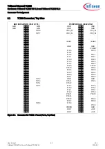
Страница 31: ...socket connectors on bottom layer The default connectors are 80 pol Board to Board connectors from Samtec http www samtec com Plug FTSH 140 02 L DV ES A Socket FLE 140 01 G DV A 6 1 On Board only used signals Following port pins are only used on board and are not connected to any connector also not via resistor Table 6 1 On Board only used Signals Short name Description P32 0 Used as VGATE1N for E...

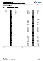
Страница 32: ...10 4 25 26 27 28 P10 2 27 28 P23 1 29 30 P13 1 29 30 P22 1 31 32 P13 0 31 32 P22 0 33 34 P13 3 33 34 P22 3 35 36 P13 2 35 36 P22 2 37 38 P20 9 37 38 P20 10 39 40 P20 13 39 40 P00 4 41 42 P33 5 41 42 P20 6 43 44 P20 3 43 44 P20 2 45 46 P00 0 45 46 P00 3 47 48 P00 1 47 48 P00 2 49 50 P21 2 GND 49 50 GND 51 52 P21 3 XTAL1 51 52 P32 4 53 54 P21 4 XTAL2 53 54 55 56 P21 5 P15 3 55 56 P15 5 57 58 P15 2 5...

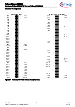
Страница 33: ... 25 26 P15 6 AN11 27 28 27 28 P15 7 AN12 29 30 29 30 AN13 31 32 P10 0 31 32 AN14 33 34 P10 1 33 34 AN15 35 36 P10 6 35 36 GND 37 38 GND 37 38 VDDM 39 40 VAREF1 39 40 GND 41 42 41 42 GND 43 44 GND 43 44 AN32 45 46 P11 2 45 46 AN33 47 48 P11 3 47 48 AN34 49 50 49 50 AN35 51 52 51 52 AN36 53 54 P11 6 53 54 AN37 55 56 55 56 P33 8 AN38 57 58 P11 8 57 58 P33 9 AN39 59 60 P11 9 59 60 P33 10 GND 61 62 GND...

Страница 34: ...10 4 25 26 27 28 P10 2 27 28 P23 1 29 30 P13 1 29 30 P22 1 31 32 P13 0 31 32 P22 0 33 34 P13 3 33 34 P22 3 35 36 P13 2 35 36 P22 2 37 38 P20 9 37 38 P20 10 39 40 P20 13 39 40 P00 4 41 42 P33 5 41 42 P20 6 43 44 P20 3 43 44 P20 2 45 46 P00 0 45 46 P00 3 47 48 P00 1 47 48 P00 2 49 50 P21 2 GND 49 50 GND 51 52 P21 3 XTAL1 51 52 53 54 P21 4 XTAL2 53 54 55 56 P21 5 P15 3 55 56 P15 5 57 58 P15 2 57 58 P...

Страница 35: ...25 26 P15 6 AN11 27 28 27 28 P15 7 AN12 29 30 29 30 AN13 31 32 31 32 AN14 33 34 P10 1 33 34 AN15 35 36 P10 6 35 36 GND 37 38 GND 37 38 VDDM 39 40 VAREF1 39 40 GND 41 42 41 42 GND 43 44 GND 43 44 AN32 45 46 P11 2 45 46 AN33 47 48 P11 3 47 48 AN34 49 50 49 50 AN35 51 52 51 52 AN36 53 54 P11 6 53 54 AN37 55 56 55 56 P33 8 AN38 57 58 P11 8 57 58 P33 9 AN39 59 60 P11 9 59 60 P33 10 GND 61 62 GND P11 10...

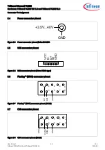
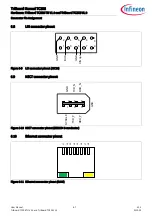
Страница 36: ...wer connector pinout Figure 6 5 Power connector pinout Roka 520 2550 6 5 USB connector pinout Figure 6 6 USB connector pinout Micro USB B type 6 6 FlexRay ERAY connector pinout Figure 6 7 FlexRay ERAY connector pinout IDC10 6 7 CAN connector pinout Figure 6 8 CAN connector pinout IDC10 3 5V 40V GND D D VCC GND ID 2 4 6 8 GND BP BM 1 3 5 7 9 1 0 2 4 6 8 GND CANH CANL 1 3 5 7 9 1 0 GND ...

Страница 37: ...onnector Pin Assignment 6 8 LIN connector pinout Figure 6 9 LIN connector pinout IDC10 6 9 HSCT connector pinout Figure 6 10 HSCT connector pinout IEE1394 6 conductor 6 10 Ethernet connector pinout Figure 6 11 Ethernet connector pinout RJ45 2 4 6 8 GND BUS VIN opt 1 3 5 7 9 1 0 GND 3 6 2 TXD_P RXD_P 1 5 4 GND GND TXD_N RXD_N SYSCLK J2 J1 J3 J4 J5 J6 J7 J8 ...

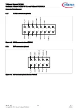
Страница 38: ...C3X6 V1 0 Connector Pin Assignment 6 11 OCDS1 connector pinout Figure 6 12 OCDS1 connector pinout IDC16 6 12 DAP connector pinout Figure 6 13 DAP connector pinout Samtec FTSH10 TDO 2 4 6 8 1 3 5 7 9 10 12 14 16 11 13 15 TDI TRST TCK BRKIN TMS GND GND PORST BRKOUT GND V_UC DAP0 2 4 6 8 1 3 5 7 9 10 USR1_IO PORST USR0_IO DAP1 GND GND Key GND V_UC ...

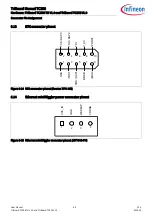
Страница 39: ...oard TC3X6 V1 0 Connector Pin Assignment 6 13 ETK connector pinout Figure 6 14 ETK connector pinout Samtec TFM 105 6 14 Ethernet miniWiggler power connector pinout Figure 6 15 Ethernet miniWiggler connector pinout JST B4B PH TDO DAP2 2 4 6 8 1 3 5 7 9 10 V_UC PORST TDI TCK DAP0 TRST TMS DAP1 BRKIO ESR0 GND 2 4 1 3 WAKEUP VDDSB VCC_IN GND ...

Страница 40: ... TriBoard Manual TC3X6 Hardware TriBoard TC3X6 TH V1 0 and TriBoard TC3X6 V1 0 Schematic and Layout 7 Schematic and Layout 7 1 Known problems 7 1 1 Known problems TriBoard TC3X6 TH V1 0 No problems known 7 1 2 Known problems TriBoard TC3X6 V1 0 No problems known 7 2 Schematic ...

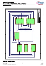
Страница 41: ... TriBoard AURIX 2G TriBoard TC3X6 TriBoard TC3X6 V1 X TriBoard_TC3X6_V10 prj File XTAL 1 2 DEBUG PORT 00 34 AN 0 39 Clock Config Debug Ports and ADC Clk_Cfg_Dbg_Ports_Adc sch PORT 00 34 ESR0 On Board Peripherals Peripherals sch DEBUG PORT 00 34 ESR0 PORST miniWiggler and Debug Connectors wiggler_Dbg_con sch PORST ESR0 ESR1 PORT 00 34 Power Supply Supply sch XTAL 1 2 PORT 00 34 AN 0 39 PORST ESR0 E...

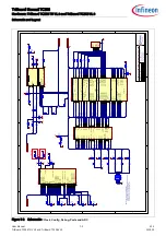
Страница 42: ...PB M3 AN13 EDS0NB N2 AN16 NC M1 AN17 NC M2 AN24 EDS2PB P40 0 NC L1 AN25 EDS2NB P40 1 NC L2 VAREF1 P4 VDDM P3 VSSM VAGND1 P2 AN36 EDS1PA P40 6 J1 AN37 EDS1NA P40 7 J2 AN38 EDS1PB P40 8 J3 AN39 EDS1NB P40 9 J4 AN9 N3 AN15 EDS3NB N1 AN14 EDS3PB L4 AN33 P40 5 K2 AN34 K3 AN35 K4 U201E TC3X6 R222 6R8 CB205 2 2μF GND VAREF1 VDDM R220 1R2 R221 1R2_opt AN0 AN1 AN2 AN3 AN4 AN5 AN6 AN8 AN10 AN11 AN12 AN13 AN...

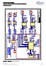
Страница 43: ..._UC VIN VIN EN 2 INH 8 BUS 6 TXD 4 WK 3 RXD 1 VS 7 GND 5 U306 TLE7259 3GE C304 1n GND P20 7 P20 8 1 2 3 4 T302 B82789 C0104 TXD 4 BGE 7 TXDEN 5 RXD 6 EN 2 STBN 8 RXEN 9 ERRN 10 GND 13 INH 1 WAKE 12 BP 15 BM 14 VBAT 11 VDD 16 VIO 3 U303 TLE9221SX GND INHA GND GND TXD 4 BGE 7 TXDEN 5 RXD 6 EN 2 STBN 8 RXEN 9 ERRN 10 GND 13 INH 1 WAKE 12 BP 15 BM 14 VBAT 11 VDD 16 VIO 3 U304 TLE9221SX GND INHB GND GN...

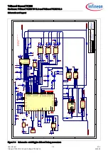
Страница 44: ...US0 ACBUS1 ACBUS5 ACBUS6 BDBUS0 BDBUS1 1 3 D403 BAT54 USR8 GND R420 4K7 V_UC DAP1_A TDI TRST DAP0_A DAP1_A P15 3 P15 2 BDBUS0 BDBUS1 CB409 100n R412 680R D402 LP T67K VDD_FT R414 4K7 R416 10K R418 10K R417 10K R419 10K VDD_FT V_UC VDD_FT V_UC R415 10K V_UC R410 10K VDD_FT R421 opt R422 opt GND GND R440 0R_opt GND GND 1 3 Y401 NX3225SA 12MHz C404 8pF C405 8pF VDD_FT GND GND R441 10K VDD_FT GND VDD_...

Страница 45: ...C507 1μF 10V GND C512 4 7μF GND V_UC QT1 QT2 GND R507 100K PORST 1 3 2 Q505 BSS138N ESR1 P14 2 GND P02 7 C503 22μF 10V C508 4 7μF C509 4 7μF C510 4 7μF C511 4 7μF GND GND V_STBY R506 100K GND R502 10K P33 8 D502 SS26 VDD_USB L501 XAL5050 223MEB L502 XAL4030 472MEC R501 250mR 4 3 1 2 5 6 Q501 BSL606SN C501 47μF 40V GND GND GND D503 SS22_opt GND R508 0R R509 20K GND V_CO CB502 100n R504 470R D508 LP...

Страница 46: ... NC2 11 NC2 13 ESR1 P15 3 P15 2 P20 14 P20 12 NC2 10 NC2 14 PORST XTAL1 XTAL2 NC2 12 P15 5 P15 1 P15 0 P14 0 P14 1 P15 4 P20 11 NC2 18 NC2 54 P15 8 NC2 73 NC2 72 P10 3 NC2 21 P10 5 P23 3 P10 2 P23 1 P13 1 P13 0 P13 3 P13 2 P10 4 P22 1 P22 0 NC2 26 P20 9 P20 10 P20 13 P00 4 P20 3 P20 6 P33 5 P20 2 P00 0 P00 1 P00 2 P00 3 NC2 66 P00 5 P00 12 P32 4 NC2 5 80 NC1 5 80 NC1 5 80 NC2 5 80 XTAL 1 2 V_UC 3V...

Страница 47: ...NC1 29 NC1 31 NC1 33 NC1 35 NC1 37 NC1 39 NC1 41 NC1 43 NC1 45 NC1 47 NC1 49 NC1 51 NC1 53 NC1 55 NC1 57 NC1 59 NC1 61 NC1 63 NC1 65 NC1 67 NC1 69 NC1 71 NC1 73 NC1 75 NC1 77 P21 0 P21 6 P21 7 NC1 10 NC1 12 NC1 14 NC1 16 NC1 18 NC1 20 NC1 22 NC1 24 NC1 26 NC1 28 NC1 30 NC1 32 NC1 34 NC1 36 NC1 38 NC1 40 NC1 42 NC1 44 NC1 46 NC1 48 P21 2 P21 3 P21 4 P21 5 NC1 58 NC1 60 NC1 62 NC1 64 NC1 66 NC1 68 N...

Страница 48: ...1 R401 L 401 BU 401 C402 CB405 X406 R457 R249 R248 R246 R245 R244 X402 S201 R377 CB20 2 R204 R205 X305 X304 X303 R236 R234 R232 R230 R36 1 R359 R212 D301 C3 03 U4 08 U4 07 U4 06 R451 R455 R 4 56 R454 R446 R444 CB419 CB418 CB417 CB416 CB415 CB414 D40 1 R430 R429 R423 R411 D4 02 U404 CB402 R34 4 R424 R425 R426 R427 R428 R20 1 R203 R20 2 C 2 01 C 2 02 R206 R 207 Y201 R337 R357 R324 R399 R391 R 3 92 R...

Страница 49: ... R4 05 R440 CB409 R416 R418 R419 R4 14 R420 C40 6 Q4 02 Q403 C404 C4 05 CB410 CB411 CB412 R4 41 R44 2 C 401 R404 C403 CB413 L4 02 U405 R4 33 C51 8 R431 R208 R408 R215 R214 U306 R521 R240 R364 R363 R362 R360 R211 CB3 10 C304 R449 R448 R447 R445 R443 R413 D403 R450 R422 R421 U 4 03 Q40 1 R412 R415 R410 R409 CB407 R407 U4 02 R406 CB40 6 R305 R30 6 R308 R309 R315 R 316 R318 R319 R30 1 R31 1 R 3 41 R34...

Страница 50: ...1 L 401 BU 401 C402 CB405 X406 R457 R249 R248 R246 R245 R244 X402 S201 R377 CB202 R204 R205 X305 X304 X303 R236 R234 R232 R230 R36 1 R359 R212 D301 C3 03 U4 08 U4 07 U4 06 R451 R455 R 4 56 R454 R446 R444 CB419 CB418 CB417 CB416 CB415 CB414 D40 1 R430 R429 R423 R411 D4 02 U404 CB402 R34 4 R424 R425 R426 R427 R428 R20 1 R203 R20 2 C 2 01 C 2 02 R206 R 207 Y201 R337 R357 R324 R399 R391 R 3 92 R3 93 R...

Страница 51: ...B 404 R4 05 R440 CB409 R416 R418 R419 R4 14 R420 C40 6 Q4 02 Q403 C404 C4 05 CB410 CB411 CB412 R4 41 R44 2 C 401 R404 C403 CB413 L4 02 U405 R4 33 C518 R431 R208 R408 R215 R214 U306 R521 R240 R364 R363 R362 R360 R211 CB3 10 C304 R449 R448 R447 R445 R443 R413 D403 R450 R422 R421 U 4 03 Q40 1 R412 R415 R410 R409 CB407 R407 U4 02 R406 CB40 6 R305 R30 6 R308 R309 R315 R 316 R318 R319 R30 1 R31 1 R 3 41...

Страница 52: ...iBoard TC3X6 V1 0 2019 09 TriBoard Manual TC3X6 Hardware TriBoard TC3X6 TH V1 0 and TriBoard TC3X6 V1 0 Schematic and Layout Layout with Dimensioning The following dimensions should be used for development of extension boards Figure 7 12 Dimensioning mm ...

Страница 53: ...riBoard TC3X6 TH V1 0 and TriBoard TC3X6 V1 0 2019 09 TriBoard Manual TC3X6 Hardware TriBoard TC3X6 TH V1 0 and TriBoard TC3X6 V1 0 Schematic and Layout Figure 7 13 Dimensioning mil The dimensioning is valid for all TriBoards ...

Страница 54: ...TriBoard TC3X6 TH V1 0 and TriBoard TC3X6 V1 0 2019 09 TriBoard Manual TC3X6 Hardware TriBoard TC3X6 TH V1 0 and TriBoard TC3X6 V1 0 Revision History Page or Item Subjects major changes since previous revision V1 0 2019 09 First version ...

Страница 55: ... of any kind including without limitation warranties of non infringement of intellectual property rights of any third party In addition any information given in this document is subject to customer s compliance with its obligations stated in this document and any applicable legal requirements norms and standards concerning customer s products and any use of the product of Infineon Technologies in ...

Отзывы: