User Manual
4-1
V1.0
TriBoard TC3X6 TH V1.0 and TriBoard TC3X6 V1.0
2019-09
TriBoard Manual TC3X6
Hardware: TriBoard TC3X6 TH V1.0 and TriBoard TC3X6 V1.0
TriBoard Configuration
4
TriBoard Configuration
4.1
HW Boot Configuration
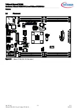
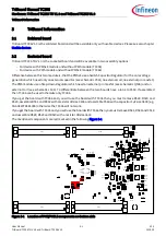
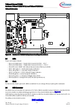
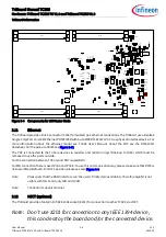
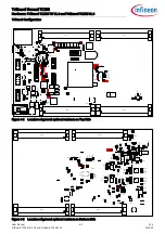
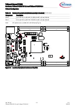
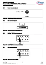
Figure 4-1 HW Configuration DIP-Switches
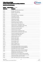
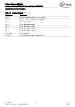
The picture above shows the definition of the boot HW configuration switch. The meaning of the switches will be
described in the following table (
).
Note:
The ON position of the switch is equal to a logical LOW at the dedicated pin.
4.1.1
Default Pad State
P14.4 / HWCFG6 is used to select the Default Pad State. Dipswitch 1 used to select this.
In case that dispswitch1 is set to ON then all I/O pins are in tristate otherwise the internal pull-up devices are
enabled on the I/O pins. Please note that after change Dipswitch 1 you must make a power cycle (switch off ->
switch on) to use the new configuration.
In case that TriState is selected (Dipswitch 1 is set to ON) then the I/O pins are floating. If you need a specific level
on different pins during startup (e.g. driver pins) then you must add the needed pull device (up or down). Some
pins (especially the HWCFG pins) haven always the needed external pull-up and/or pull-down resistor assembled
on the board.
4.1.2
Bootmode
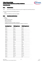
Table 4-1
User Startup Modes
1)2)3)
1) The shadowed line indicates the default setting.
2) ’x’ represents the don’t care state.
3) 2 to 4 are the Dip Switch numbers.
HWCFG[5...3]
Type of Boot
2
3
4
XX1
Start-up mode is selected by Boot Mode Index
X
X
OFF
110
Internal Start from Flash
OFF OFF ON
100
Alternate Boot Mode, Generic Bootstrap Loader on fail (P14.0/P14.1)
ON
OFF ON
010
Alternate Boot Mode, ASC Bootstrap Loader on fail (P15.2/P15.3)
OFF ON
ON
000
Generic Bootstrap Loader (P14.0/P14.1)
ON
ON
ON
2
on
1
3
4
P1
4.
4
P
10.
5
P1
0.
6
P1
4.
3

