


XC161 Derivatives
Peripheral Units (Vol. 2 of 2)
The General Purpose Timer Units
User’s Manual
14-21
V2.2, 2004-01
GPT_X1, V2.0
For counter operation, pin TxIN must be configured as input (the respective direction
control bit DPx.y must be 0). The maximum input frequency allowed in counter mode
depends on the selected prescaler value. To ensure that a transition of the count input
signal applied to TxIN is recognized correctly, its level must be held high or low for a
minimum number of module clock cycles before it changes. This information can be
found in
Timers T2 and T4 in Incremental Interface Mode
Incremental interface mode for an auxiliary timer Tx is selected by setting bitfield TxM in
the respective register TxCON to 110
B
or 111
B
. In incremental interface mode, the two
inputs associated with an auxiliary timer Tx (TxIN, TxEUD) are used to interface to an
incremental encoder. Tx is clocked by each transition on one or both of the external input
pins to provide 2-fold or 4-fold resolution of the encoder input.
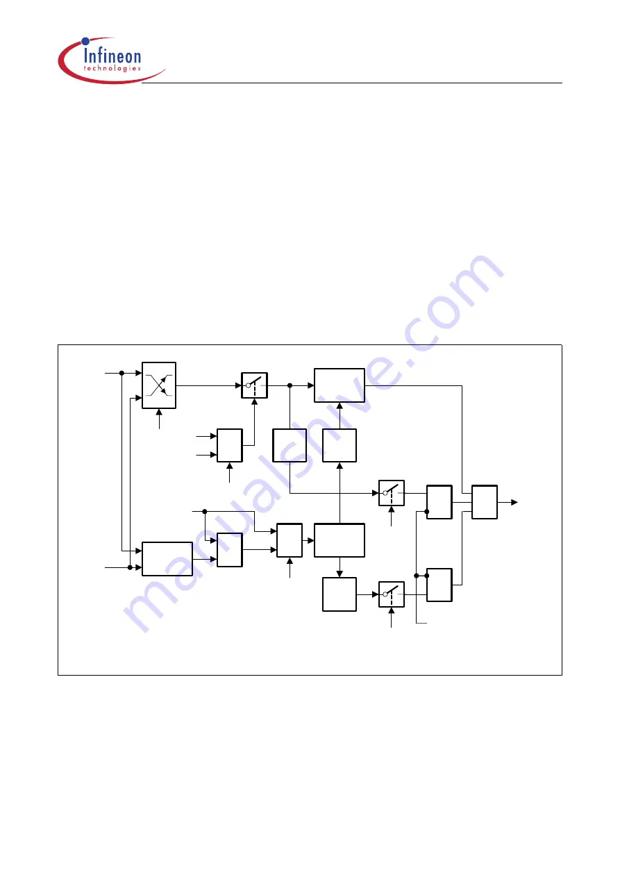
Figure 14-14 Block Diagram of an Auxiliary Timer in Incremental Interface Mode
The operation of the auxiliary timers T2 and T4 in incremental interface mode and the
interrupt generation are the same as described for the core timer T3. The descriptions,
figures and tables apply accordingly.
MCB05398
Count
Overflow
Underflow
TxEUD
Tx
Edge
Tx
RDIR
MUX
0
1
=1
TxUD
TxUDE
Change
Detect
&
TxCH
DIR
TxM
TxM
&
>1
_
Phase
Detect
MUX
TxRC
TxR
T3R
TxIN
TxI
TxIRDIS
TxIRQ
Auxiliary
Timer Tx
0
1
Edge
Select


