background image


19 - 1

PN

 07

4-

55

8-

P1

A

3000 Micro GC Guides        

3000 Micro GC Guide 19

Changing a Performance Enhanced Module

Table 19-1  Changing a Performance Enhanced module

Step

Description

1

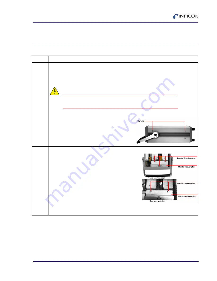
To replace a Performance Enhanced module with another Performance Enhanced module, turn 
of the instrument by setting the front panel power switch to the Off position. Remove the two 
screws on each side of the top cover using a Torx T-20 or Phillips Head screwdriver. Lift and 
remove the top cover. 

WARNING - Risk Of Electric Shock

Electrostatic Discharge can damage electronic components. Wear 
a grounded wrist strap to avoid damaging 3000 Micro GC.

2

Loosen the thumbscrews in the manifold cover plate.

3

Remove the manifold cover plate. Slide the manifold cover plate towards the GC module to 
disengage the hook in the cover plate from the tab in the chassis.

Содержание 074-558-P1A

Страница 1: ...R E F E R E N C E G U I D E 3000 Micro GC Gas Analyzer PN 074 558 P1A Cover Page ...

Страница 2: ......

Страница 3: ...www inficon com reachus inficon com 2013 INFICON R E F E R E N C E G U I D E 3000 Micro GC Gas Analyzer PN 074 558 P1A Title Page ...

Страница 4: ...re trademarks or registered trademarks of their respective companies Disclaimer The information contained in this manual is believed to be accurate and reliable However INFICON assumes no responsibility for its use and shall not be liable for any special incidental or consequential damages related to the use of this product Due to our continuing program of product improvements specifications are s...

Страница 5: ...rence Guide 3000 Micro GC Guides are not intended to replace the 3000 Micro GC Operating Manual PN 074 519 P1 or 3000 Micro GC training but are intended for use as supporting materials for those who have been trained in an INFICON sanctioned training course ...

Страница 6: ...INT These messages provide insight into product usage DANGER Failure to heed these messages may result in serious personal injury or death WARNING Failure to heed these messages could result in personal injury WARNING Risk Of Electric Shock Dangerous voltages are present Failure to heed these messages could result in personal injury CAUTION Failure to heed these messages could result in damage to ...

Страница 7: ...ntact an INFICON Sales office or Repair Service to contact an INFICON Service Center is available at www inficon com If experiencing an instrument problem please have the following information readily available the instrument serial number a description of the problem an explanation of any corrective action that may have already been attempted and the exact wording of any error messages observed T...

Страница 8: ...PN 074 558 P1A 3000 Micro GC Guides This page is intentionally blank ...

Страница 9: ...o 3000 Micro GC via the Crossover Cable 1 1 3000 Micro GC Guide 2 Connecting to 3000 Micro GC via the Static IP Address 2 1 3000 Micro GC Guide 3 Changing the Instrument IP Address 3 1 3000 Micro GC Guide 4 Changing the Carrier Gas Configuration 4 1 3000 Micro GC Guide 5 Installing EZ IQ 5 1 3000 Micro GC Guide 6 Configuring a 3000 Micro GC with EZ IQ 6 1 3000 Micro GC Guide 7 3000 Micro GC Method...

Страница 10: ...libration with Average Replicates 15 1 3000 Micro GC Guide 16 Customizing a Method Report 16 1 3000 Micro GC Guide 17 Customizing an ESTD Report 17 1 3000 Micro GC Guide 18 Changing a Standard Module 18 1 3000 Micro GC Guide 19 Changing a Performance Enhanced Module 19 1 3000 Micro GC Guide 20 Replacing a Standard Module with a Performance Enhanced Module 20 1 3000 Micro GC Guide 21 Testing Instru...

Страница 11: ...ship kit to a TCP IP ethernet port on the PC Connect the other end to the ethernet port on the back of 3000 Micro GC 2 Turn the 3000 Micro GC power switch located on its front to the on position The switch will illuminate green to indicate that 3000 Micro GC is on Wait three minutes for the instrument to load 3 Click Windows Start Connect to Show All Connections NOTE Depending on the version of Wi...

Страница 12: ...s window click Properties 6 In the Local Area Connection Properties window in The connection uses the following items area select Internet Protocol TCP IP then click Properties Table 1 1 Configuring a PC for a direct connection via the crossover cable continued Step Description ...

Страница 13: ...k 255 255 255 0 Default gateway The Default gateway can remain blank for a direct connection via the crossover cable 9 Click OK to exit the Internet Protocol TCP IP Properties window 10 Click OK to exit the Local Area Connection Properties window 11 Click Close to exit the Local Area Connection Status window Table 1 1 Configuring a PC for a direct connection via the crossover cable continued Step ...

Страница 14: ...ata packets from the instrument NOTE If the command prompt reads Request Timed Out or Detection Limit Unreachable repeat steps 3 to 7 to verify IP settings Verify that 3000 Micro GC is turned on and connected to the PC via the crossover cable If there is still no communication contact INFICON Table 1 1 Configuring a PC for a direct connection via the crossover cable continued Step Description ...

Страница 15: ...ress via a direct crossover cable in order to avoid potential routing issue in a local area network LAN 2 Connect one end of the crossover cable PN 5183 4649 provided in the ship kit to a TCP IP ethernet port on the PC Connect the other end to the ethernet port on the back of 3000 Micro GC 3 The 3000 Micro GC power switch is located on its front panel Turn the switch to the on position The switch ...

Страница 16: ...s window click Properties 7 The Local Area Connection Properties window will display Select Internet Protocol TCP IP in The connection uses the following items area then click Properties Table 2 1 Connecting to the instrument via the static IP address continued Step Description ...

Страница 17: ...et Mask 255 255 255 0 Default gateway The Default gateway can remain blank for a direct connection via the crossover cable 10 Click OK to exit the Internet Protocol TCP IP Properties window 11 Click OK to exit the Local Area Connection Properties window 12 Click Close to exit the Local Area Connection Status window Table 2 1 Connecting to the instrument via the static IP address continued Step Des...

Страница 18: ...ion Limit Unreachable repeat steps 3 to 7 to verify IP settings Verify that 3000 Micro GC is on connected to the PC via the crossover cable If there is still no communication contact INFICON 16 Open a web browser such as Internet Explorer 17 In the address bar type 192 168 1 99 and press Enter 18 The instrument embedded web page will display Select the IP Configuration tab Review the IP address Ta...

Страница 19: ... professional to assist with IP settings 2 Open a web browser such as Internet Explorer 3 In the address bar type the current IP Address of the instrument Press Enter NOTE The factory default IP address is set at 10 1 1 101 4 The instrument s embedded web page will display Click the IP Configuration tab The current IP address for the instrument is displayed Click Make Changes 5 When prompted for a...

Страница 20: ...update configuration files CAUTION Do not turn off the power without waiting three minutes 3000 Micro GC must update configuration files before power is turned off If power is turned off too soon the files could be corrupted and render 3000 Micro GC unusable 8 Connect to the instrument using the new IP address Click Windows Start Run 9 In the Run window in the Open box type the new IP address Clic...

Страница 21: ...3000 Micro GC via the Static IP Address If connecting to the static IP address of the instrument is unsuccessful contact the network administrator to check whether there is a conflict of the newly assigned IP address or any possible network issue between the instrument and the PC Once the network issue is resolved perform steps in this section again to configure the instrument to the new IP addres...

Страница 22: ...3 4 PN 074 558 P1A 3000 Micro GC Guides This page is intentionally blank ...

Страница 23: ...thout following this procedure inverted peaks will appear in the chromatogram 2 Open a web browser such as Internet Explorer 3 In the address bar type in the current 3000 Micro GC IP Address Press Enter NOTE At the factory the instrument IP address was set to 10 1 1 101 4 The instrument s embedded webpage will display Click the Gas Type tab The current gas configuration for installed GC modules is...

Страница 24: ...3 and m4 represent channels C and D if installed NOTE In the example shown above carrier1 is assigned to modules m1 and m2 Carrier2 is unused 7 Select the new carrier gas type from the drop down list Click Submit 8 The column heaters will turn off to avoid thermal shock and degradation Click Check Status to view the current column temperatures Table 4 1 Changing the carrier gas configuration conti...

Страница 25: ...tes for the instrument to update configuration files CAUTION Do not turn off the power without waiting at least three minutes 3000 Micro GC must update configuration files before power is turned off If power is turned off too soon the files could be corrupted and render 3000 Micro GC unusable 12 To run samples using the reconfigured gas type click Windows Start Programs Chromatography EZ IQ Config...

Страница 26: ...4 4 PN 074 558 P1A 3000 Micro GC Guides This page is intentionally blank ...

Страница 27: ...Installer window will display If it does not display double click CDInstaller exe under the CD ROM root drive 2 Click Install EZ IQ to start the installation 3 The EZ IQ Setup Welcome window will display Click Next 4 The EZ IQ Setup Choose Destination Location window will display Choose an EZ IQ software installation destination folder The default destination folder is C EZIQ Click Next ...

Страница 28: ...in a name for the program folder This name will be shown in the Windows Start All Programs menu Use the default Chromatography program folder name Click Next 6 The EZ IQ Setup Setup Status window will display 7 When prompted click Yes to create an EZ IQ program desktop short cut Table 5 1 Installing EZ IQ continued Step Description ...

Страница 29: ... EZ IQ Setup Reboot to Complete Setup window will display Click Yes I want to restart my computer now Click Finish 9 After the computer has restarted the Data System window will display Click OK to complete the installation Table 5 1 Installing EZ IQ continued Step Description ...

Страница 30: ...5 4 PN 074 558 P1A 3000 Micro GC Guides This page is intentionally blank ...

Страница 31: ...trument Configuration window type an Instrument name select Instrument type 3000 Micro GC Enhanced Driver and click Configure NOTE This guide outlines the procedure to configure the 3000 Micro GC Enhanced Driver For the 3000 Micro GC Classic Driver see the appropriate chapter in the PN 074 538 P1 EZ IQ Operating Manual 4 The 3000 Micro GC Enhanced Driver window will display Under Available modules...

Страница 32: ...Load Configuration from GC Once the 3000 Micro GC configuration has been properly loaded into EZ IQ a Configuration loaded successfully from GC device or GC Configuration Available message will display 7 Click OK to exit the INFICON 3000 Micro GC Configuration window 8 Click OK to exit the INFICON 3000 Micro GC Enhanced Driver window 9 Click OK to exit the Instrument Configuration window 10 Click ...

Страница 33: ...C Method Setup Table 7 1 Creating a method Step Description 1 It is possible to either create a new method or open an existing method in EZ IQ Click File Method and select either New or Open from the drop down list 2 To edit method parameters click Method Instrument Setup ...

Страница 34: ...Pump time Column Pressure etc Ensure that the Run Time is long enough for the last expected peak to elute If the elution time is unknown conduct a run and verify the presence of the last expected peak If necessary increase the Run Time The default Inject Time should be set between 0 50 ms for a fixed volume injector 0 100 ms for a variable volume injector 0 350 ms for a variable large volume injec...

Страница 35: ...be triggered by an external event through a remote control connection select External 5 To save the method click File Method Save to overwrite the existing method file or Save As to save a new method file 6 When a new method is created or when a method is changed or opened it must be downloaded to 3000 Micro GC Click Control Download Method Table 7 1 Creating a method continued Step Description ...

Страница 36: ... instrument NOTE The status will read Not Ready highlighted in yellow if paramters have not reached their set points Parameters that are changing are highlighted in yellow A run cannot be started unless the status reads Ready highlighted in green Table 7 1 Creating a method continued Step Description ...

Страница 37: ...iption 1 To start the run click Control Single Run 2 The Single Run Acquisition window will display In the Sample ID box type a Sample ID 3 The method will default to the method that is currently loaded To change the method click the folder icon located on the right of the Method box and select the desired method ...

Страница 38: ...filename To automatically include certain descriptors such as Sample ID Method Name and Date and Time click the blue arrow located to the right of the Data File field Select the desired descriptors 6 In the Number of Reps box type the desired number of repetitions 7 Click Start to begin a run Data will be displayed in the chromatogram window Table 8 1 Running a sample continued Step Description ...

Страница 39: ...l events In EZ IQ click Method Integration Events 2 Select a channel to add or edit integration events To change the channel select the appropriate channel from the drop down list on the toolbar 3 The Integration Events window will display the default integration events 4 To add a new event click on a blank field under Event in the table Select the desired integration event from the drop down list...

Страница 40: ...9 2 PN 074 558 P1A 3000 Micro GC Guides This page is intentionally blank ...

Страница 41: ...ks or Groups from the drop down list 5 On the Available Annotations list select the features to annotate For example select Retention Time to display the retention time above the integrated peaks 6 When an annotation is highlighted double click the annotation or click the green arrow key to move it from Available Annotations to Show the following annotations NOTE For certain annotations the number...

Страница 42: ...the check boxes to display Baseline USP Width Retention Time Window Show Undetected Named Peaks or Group Range on the chromatogram 8 When finished selecting annotations click Apply to All or OK Table 10 1 Setting Annotations continued Step Description ...

Страница 43: ...ks and Groups Table 11 1 Qualify peaks and groups Step Description 1 Once a run is finished peaks and groups can be identified based on retention time Select a channel to add or edit peak or group information from the drop down list on the tool bar 2 Click Method Peaks Groups ...

Страница 44: ...ange Click the blue arrow on the right of the Group Def field The Group Range Definition window will display Type a Region Start and Region Stop in minutes or seconds NOTE In the example Region Start and Region Stop are displayed in seconds Ensure that Calculate Concentrations for Unnamed Peaks in Group is selected from the drop down list Click OK to return to the Groups tab 4 Repeat Steps 1 to 3 ...

Страница 45: ...Retention Time Windows Table 12 1 Adjusting retention time windows Step Description 1 In EZ IQ click the Adjust Retention Time Window icon on the Int Events tool bar Alternatively right click on the chromatogram and click Graphical Programming Adjust Retention Time Window ...

Страница 46: ...ick directly on the desired retention time window HINT Click and drag from the corner of the window to resize 3 Press Esc to display the Adjust Retention Time Window option Click Analyze Now to apply the changes and exit the window Table 12 1 Adjusting retention time windows continued Step Description ...

Страница 47: ... sample of a calibration gas i e a sample with known component concentrations The generated data file can be used to define the calibration peaks 3 Connect the calibration gas to the front inlet of 3000 Micro GC Ensure that the calibration gas output pressure and the 3000 Micro GC inlet is properly regulated to between 1 25 PSI Open the gas cylinder to begin flow to the instrument 4 Click Control ...

Страница 48: ...so click the Open file icon adjacent to the field 12 In the Data file box select the file name if not already present To do so click the Open file icon adjacent to the field 13 The Amount values will remain set at 1 a value of 1 corresponds to a single level calibration 14 Select Calibrate In the Calibration Level box type 1 NOTE For the initial calibration it is not necessary to select any of the...

Страница 49: ...he areas for the peaks identified as calibration compounds will be entered into the method In addition a calibration curve will be generated using these areas The method is now calibrated for a single level 17 To save the calibration to the method click File Method Save Table 13 1 Conduct a single level calibration continued Step Description ...

Страница 50: ...13 4 PN 074 558 P1A 3000 Micro GC Guides This page is intentionally blank ...

Страница 51: ... all peaks and groups in each of the channels NOTE Each level represents one calibration gas standard Select a channel to add or edit calibration information via the dropdown list on the tool bar 4 Connect the calibration gas Ensure that the tank is properly regulated to between 1 25 PSI if going direct to the 3000 Micro GC inlet Turn on the desired calibration gas Connect the calibration gas to t...

Страница 52: ...ld and selecting the desired data path 11 In the Data file box select the file name if not already present by clicking the Open file icon adjacent to the field 12 The Amount values are to remain set to 1 a value of 1 corresponds to a single level calibration 13 Select Calibrate In the Calibration level box type 1 NOTE For the initial calibration it is not necessary to select any of the boxes invol...

Страница 53: ...brated for one of the desired levels 16 Repeat steps 4 to 15 to calibrate other levels one level at a time 17 After completing a calibration in the window click Method Review Calibration to review the calibration curve and its associated data Each peak will have its own calibration curve If desired right click on a blank area to bring up options such as View Fit Type Change Fit Type and a Concentr...

Страница 54: ...14 4 PN 074 558 P1A 3000 Micro GC Guides This page is intentionally blank ...

Страница 55: ...e the Calib Flag to Wt Average using the drop down list Enter 100 for the Calib Weight Repeat for each component in each channel NOTE Select a channel from the drop down list on the toolbar to add or edit calibration information 3 Connect the calibration gas to the front inlet of 3000 Micro GC Ensure that the calibration gas output pressure is properly regulated between 1 25 PSI Open the gas cylin...

Страница 56: ...jacent to the field and selecting the desired data path 11 In the Data file box select the file name if not already present by clicking the Open file icon adjacent to the field 12 The Amount values are to remain set to 1 a value of 1 corresponds to a single level calibration 13 Select the Calibrate setting and type 1 for Calibration Level Select Average replicates NOTE For the initial calibration ...

Страница 57: ...t each Sample ID is unique for example calgas1rep2 calgas1rep3 etc 17 After completing a calibration in the window a calibration curve and associated data can be reviewed by clicking Method Review Calibration Each peak will have its own calibration curve If desired right click on a black area on the window and select commands such as View Fit Type Change Fit Type and a Concentration Calculator The...

Страница 58: ...point represents a single replicate and a green point represents the average of the replicates Left clicking on a single blue point will turn the point red and remove it from the average calculation Table 15 1 Conducting a calibration with replicates continued Step Description ...

Страница 59: ...phs and data click Method Custom Report 2 A method report window will display 3 Sections can be added to the report by right clicking anywhere on the method report Select the desired options such as Insert Field Insert Graph Insert Report or Insert Object 4 EZ IQ contains various pre made template files To import a template file right click in the method report window Select Import Report ...

Страница 60: ...rp shown below Click Open to load the template file 6 To edit the template right click and insert options such as Insert Field Insert Graph Insert Report and Insert Object 7 Once all desired information has been modified or added right click in the Method Report and select Export Report Table 16 1 Customize a report continued Step Description ...

Страница 61: ...he File Name box type a method report name Click Save 9 To view the custom method report select Reports View Method Report 10 To print the custom Method Report right click in the Method Report window then select Print from the drop down list Table 16 1 Customize a report continued Step Description ...

Страница 62: ...16 4 PN 074 558 P1A 3000 Micro GC Guides This page is intentionally blank ...

Страница 63: ...on It is not method specific The same template will be applied to any method that is opened 2 Click Method Custom Report A method report window will display 3 To import the ESTD Report file right click in the method report window and select Import Report from the dropdown list 4 The Open Report Template File window will display Select External Standard srp and click Open to load the template file ...

Страница 64: ...sert Object 6 Once all desired information has been modified or added right click in the Method Report window and select Export Report 7 The Save Method Custom Report As window will open Click External Standard srp Click Save Click Yes to overwrite the current file Table 17 1 Customizing an external standard ESTD report continued Step Description ...

Страница 65: ...ew the ESTD report click Reports View External Standard 9 To print the ESTD Report right click in the Method Report window and select Print from the drop down list Table 17 1 Customizing an external standard ESTD report continued Step Description ...

Страница 66: ...17 4 PN 074 558 P1A 3000 Micro GC Guides This page is intentionally blank ...

Страница 67: ...hannel or portable instrument the module addresses are 1 and 2 For a 3 4 channel instrument the module addresses are 1 2 3 and 4 Decommissioning a Standard GC module will disable the GC module s address Open the web browser and type the 3000 Micro GC IP Address in the address bar press Enter to display the embedded web page NOTE At the factory the instrument IP address is set to 10 1 1 101 2 Click...

Страница 68: ...ain until it is recommissioned 4 Click Remove adjacent to the desired Standard GC module to be decommissioned A caution will display Click OK to decommission the Standard GC module 5 Click Shutdown on the confirmation message to begin shutting down the instrument Table 18 1 Changing a standard module continued Step Description ...

Страница 69: ... turned off If power is turned off too soon the files could be corrupted making 3000 Micro GC unusable 7 Set the front panel power switch to the Off position 8 Remove the two screws on each side of the top cover using a Torx T 20 or Phillips Head screwdriver Lift and remove the top cover WARNING Risk Of Electric Shock Electrostatic Discharge can damage electronic components Wear a grounded wrist s...

Страница 70: ...1 Carefully remove the manifold insulation and save it for reuse NOTE In the Portable 3000 Micro GC the DC DC converter assembly blocks access to the GC modules Remove the screws that secure the DC DC converter assembly to the side of the instrument Without disconnecting any wires slide the assembly off of the standoffs and gently lift it away from the GC modules Table 18 1 Changing a standard mod...

Страница 71: ...tion cables leading from the GC modules if connected from the GC module communications board Disconnect the power cables leading to the fan if installed Table 18 1 Changing a standard module continued Step Description Loosen screw Manifold fitting screw 2 channel 3000 Micro GC shown Others are similar GC module Inlet Disconnect inlet fittings 2 channel 3000 Micro GC shown Others are similar manifo...

Страница 72: ... the bottom of the chassis to make sure the mating surface is free of dust and particles 17 On the replacement module remove the small metal plate covering the O rings on the upper gang block Table 18 1 Changing a standard module continued Step Description Tilt GC module Mounting flange Mounting flange Tilt until mounting flange is free from aligning pins 2 channel 3000 Micro GC shown Others are s...

Страница 73: ...erify all new O rings on the replacement GC module are undamaged and seated flat 19 Use a wrench to loosen the protective 1 4 in cap over the GC module inlet fitting Table 18 1 Changing a standard module continued Step Description Verify O ring placement Mounting flange Gang block upper half ...

Страница 74: ...ime ensure the GC module inlet fitting mates with the Swagelok fitting in the 3000 Micro GC inlet manifold Slide the GC module towards the front of 3000 Micro GC until it is fully seated into the Swagelok fitting in the 3000 Micro GC inlet manifold Table 18 1 Changing a standard module continued Step Description Install GC below frame Mate module fittings View from back of 3000 Micro GC manifold m...

Страница 75: ...in the mounting flange 24 Carefully replace the inlet manifold insulation 25 Install the manifold cover plate and the top cover 26 For Standard GC modules a new address must be given to the newly installed GC module This can be done via the embedded web page Turn the 3000 Micro GC power switch located on its front to the On position The switch will illuminate green to indicate that 3000 Micro GC i...

Страница 76: ...nge Module Configuration 30 Click Set 31 Use the drop down list on the lower left portion of the screen to select the correct physical address for the new standard GC module Each physical address corresponds to a channel number Valid 3000 Micro GC physical addresses are 1 through 4 Table 18 1 Changing a standard module continued Step Description ...

Страница 77: ...urned off If power is turned off too soon the files could be corrupted and render 3000 Micro GC unusable 34 Open the web browser and type the 3000 Micro GC IP Address in the address bar Verify that the recently installed replacement module is available in the module list 35 Once the replacement standard module is installed update EZ IQ with the revised 3000 Micro GC hardware configuration For deta...

Страница 78: ...18 12 PN 074 558 P1A 3000 Micro GC Guides This page is intentionally blank ...

Страница 79: ...itch to the Off position Remove the two screws on each side of the top cover using a Torx T 20 or Phillips Head screwdriver Lift and remove the top cover WARNING Risk Of Electric Shock Electrostatic Discharge can damage electronic components Wear a grounded wrist strap to avoid damaging 3000 Micro GC 2 Loosen the thumbscrews in the manifold cover plate 3 Remove the manifold cover plate Slide the m...

Страница 80: ...doffs and gently lift it away from the GC modules 5 Use a T 20 screwdriver to loosen the screw in the inlet manifold fitting at the back of the GC module 6 Use a 1 4 in open ended wrench to disconnect the inlet manifold fitting from the GC module input fitting Table 19 1 Changing a Performance Enhanced module continued Step Description 2 channel 3000 Micro GC shown Others are similar Loosen screw ...

Страница 81: ...ck of the instrument until it clears the inlet manifold frame and can be lifted and removed from the front 9 Inspect the gang block fitting on the bottom of the chassis to ensure the mating surface is clean Table 19 1 Changing a Performance Enhanced module continued Step Description Back of GC Remove cable Remove cables Communication board Back view of GC modules module Tilt GC module Mounting fla...

Страница 82: ...ate configuration Each setting determines a unique module address Please refer to the label on the top of the module The DEF setting is the factory default DIP switch setting 11 Remove the small metal plate covering the O rings on the upper gang block Table 19 1 Changing a Performance Enhanced module continued Step Description Metal plate covering O rings and upper gang block Retaining screw ...

Страница 83: ... verify all new O rings on the replacement GC module are undamaged and seated flat 13 Remove the protective 1 4 in cap over the GC module inlet fitting Table 19 1 Changing a Performance Enhanced module continued Step Description Verify O ring placement Mounting flange Gang block upper half ...

Страница 84: ...sure the GC module inlet fitting mates with the Swagelok fitting in the 3000 Micro GC inlet manifold Slide the GC module towards the front of 3000 Micro GC until it is fully seated into the Swagelok fitting in the 3000 Micro GC inlet manifold Table 19 1 Changing a Performance Enhanced module continued Step Description Install GC below frame Mate module fittings View from back of 3000 Micro GC mani...

Страница 85: ...r plate and the top cover 20 Turn the 3000 Micro GC power switch located on its front to the on position The switch will illuminate green to indicate that 3000 Micro GC is on Wait three minutes for the instrument to load 21 Open the web browser and type the 3000 Micro GC IP Address in the address bar Verify that the newly installed replacement module is available in the module list 22 Once the rep...

Страница 86: ...19 8 PN 074 558 P1A 3000 Micro GC Guides This page is intentionally blank ...

Страница 87: ...ddress For a 1 2 channel or portable instrument the module addresses are 1 and 2 For a 3 4 channel instrument the module addresses are 1 2 3 and 4 Decommissioning a Standard GC module will disable the GC module s address Open the web browser and type the 3000 Micro GC IP Address in the address bar then press Enter to display the embedded web page NOTE At the factory the instrument IP address is se...

Страница 88: ... 5 Click Remove next to the Standard GC module to decommission A caution will display Click OK to decommission the Standard GC module 6 Click Shutdown on the confirmation message Allow three minutes for the instrument to shut down 7 Set the front panel power switch to the Off position Table 20 1 Changing a standard module continued Step Description ...

Страница 89: ...wo screw design slide the manifold cover plate towards the GC module to disengage the hook in the cover plate from the tab in the chassis 11 Carefully remove the manifold insulation Save it for reuse NOTE In the Portable 3000 Micro GC the DC DC converter assembly blocks access to the GC modules Remove the screws that secure the DC DC converter assembly to the side of the instrument Without disconn...

Страница 90: ... cables leading from the GC modules if present to the communications board connectors for the GC modules If needed also disconnect the power cables leading to the fan Table 20 1 Changing a standard module continued Step Description Loosen screw Manifold fitting screw 2 channel 3000 Micro GC shown GC module Inlet Disconnect inlet fittings 2 channel 3000 Micro GC shown Others are similar manifold Ba...

Страница 91: ...e and can be lifted and removed from the front 16 Inspect the gang block fitting on the bottom of the chassis to make sure the mating surface is free of dust and particles Table 20 1 Changing a standard module continued Step Description Tilt GC module Mounting flange Mounting flange Tilt until mounting flange is free from aligning pins 2 channel 3000 Micro GC shown Others are similar Gang block lo...

Страница 92: ...riate configuration Each setting determines a unique module address Please refer to the label on the top of the module The DEF setting is the factory default DIP switch setting 18 Remove the small metal plate covering the O rings on the upper gang block Table 20 1 Changing a standard module continued Step Description Metal plate covering O rings and upper gang block Retaining screw ...

Страница 93: ...ing to verify all new O rings on the replacement GC module are undamaged and seated flat 20 Remove the protective 1 4 in cap over the GC module inlet fitting Table 20 1 Changing a standard module continued Step Description Verify O ring placement Mounting flange Gang block upper half ...

Страница 94: ...e ensure the GC module inlet fitting mates with the Swagelok fitting in the 3000 Micro GC inlet manifold Slide the GC module towards the front of the 3000 Micro GC until it is fully seated into the Swagelok fitting in the 3000 Micro GC inlet manifold Table 20 1 Changing a standard module continued Step Description Install GC below frame Mate module fittings View from back of 3000 Micro GC manifold...

Страница 95: ...ld cover plate and the top cover 27 Turn the 3000 Micro GC power switch located on its front to the on position The switch will illuminate green to indicate that 3000 Micro GC is on Wait three minutes for the instrument to load 28 Open the web browser and type the 3000 Micro GC IP Address in the address bar Verify that the recently installed replacement module is available in the module list 29 Af...

Страница 96: ...20 10 PN 074 558 P1A 3000 Micro GC Guides This page is intentionally blank ...

Страница 97: ...nt ship kit The female end will attach directly onto the column vents The ship kit also contains a 1 16 in piece of polyurethane tubing which can be attached to the male end Analytical flow rate should be 1 0 0 5 mL min Reference flow rate should be 0 6 0 4 mL min NOTE Flow rates will vary depending on column length internal diameter and film thickness 6 If no flowmeter is available a rudimentary ...

Страница 98: ...21 2 PN 074 558 P1A 3000 Micro GC Guides This page is intentionally blank ...

Страница 99: ...l I O Module PN G2847A in 3000 Micro GC and connect it to the external triggering device via a Remote Start Cable PN G2801 60618 NOTE A 4 channel 3000 Micro GC is displayed below 2 The digital I O kit contains the following items 3 The following tools are required to install the digital I O module not provided Torx T 10 driver Torx T 20 screwdriver driver Needle nose pliers helpful for disconnecti...

Страница 100: ...icking Control Instrument Status Wait until the method setpoints are reached i e the instrument is in the Ready state 6 Exit EZ IQ 7 Set the front panel power switch to the off position Disconnect the 3000 Micro GC power supply from the back of the instrument WARNING During this process the 3000 Micro GC internal components will be exposed To avoid damaging 3000 Micro GC turn the power switch off ...

Страница 101: ...Micro GC 9 Unscrew and remove the four black feet from the back panel using a Torx 20 screwdriver Retain the screws for reassembly Carefully slide the main chassis out of the back of the 3000 Micro GC until the communication board is exposed CAUTION Do not damage the ribbon cable near the upper side portion of each module 10 If removing a digital I O module refer to step 11 If installing a digital...

Страница 102: ...emove the digital I O module and ribbon cable 13 To install a digital I O module use a flat head screwdriver to pry the cover plate off the instrument s back panel 14 Slide the new Digital I O Module through the hole in the back panel so that the two threaded studs protrude through Use the retained screws to secure it in place Table 22 1 Installing the digital I O module continued Step Description...

Страница 103: ...amage any wiring or cables Use the retained screws to reassemble the top cover Attach all feet 18 Turn the 3000 Micro GC power switch located on its front to the On position The switch will illuminate green to indicate that 3000 Micro GC is on Wait three minutes for the instrument to load 19 Refer to the 074 519 3000 Micro GC Operating Manual for details on how to use the digital I O module Table ...

Страница 104: ...22 6 PN 074 558 P1A 3000 Micro GC Guides This page is intentionally blank ...

Страница 105: ...us Wait until the method setpoints are reached i e the instrument is in the Ready state 3 Shut down EZ IQ 4 Set the front panel power switch to the Off position Disconnect the 3000 Micro GC power supply from the back of the instrument WARNING During this process the 3000 Micro GC internal components will be exposed To avoid damaging 3000 Micro GC turn the power switch off and disconnect all extern...

Страница 106: ...tery cable fuse Locate Plug A Plug B and Plug C NOTE The battery cable fuse contains two Plug A connectors two Plug B connectors and one Plug C connector 10 On the replacement battery cable fuse connect both Plug A connectors to Position 1 Table 23 1 Replacing the battery cable fuse on a portable instrument continued Step Description Fuse 3AG Slow blow 10 A 32 V Type T Position 3 Position 2 Positi...

Страница 107: ... 2 13 Install the top cover of 3000 Micro GC 14 Turn the 3000 Micro GC power switch located on its front to the on position The switch will illuminate green to indicate that 3000 Micro GC is on Wait three minutes for the instrument to load Table 23 1 Replacing the battery cable fuse on a portable instrument continued Step Description ...

Страница 108: ...23 4 PN 074 558 P1A 3000 Micro GC Guides This page is intentionally blank ...

Отзывы: