Assembling the wires on the PCBs
10 - PM - Copy 1600T for iR1600 / iR2000
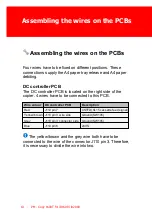
Assembling the wires on the PCBs
Four wires have to be fixed on different positions. These
connections supply the A4 paper tray release and A4 paper
debiting.
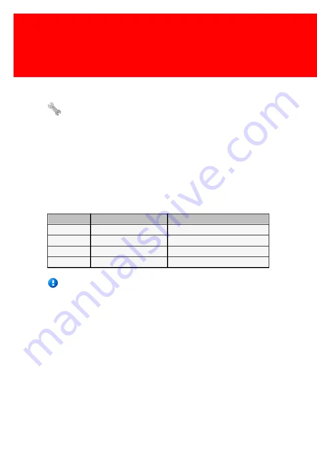
DC controller PCB
The DC controller PCB is located on the right side of the
copier. 4 wires have to be connected to this PCB.
Wire colour
DC controller PCB
Description
Red
J110 pin 7
CSTFD (SL15 cassette feed signal)
Yellow /brow n J110 pin 3 w ire side
Ground (SW105)
Grey
J110 pin 3 connector side
Ground (SW105)
Blue
J110 pin 6
24VS
The yellow/brown and the grey wire both have to be
connected to the wire of the connector J110 pin 3. Therefore,
it is necessary to divide the wire into two.
Содержание PM - Copy 1600T for iR1600
Страница 2: ......
Страница 6: ......
Страница 8: ......
Страница 9: ...I Installation Part...
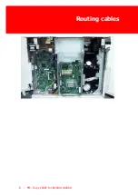
Страница 14: ...Routing cables 6 PM Copy 1600T for iR1600 iR2000...
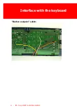
Страница 16: ...Interface with the keyboard 8 PM Copy 1600T for iR1600 iR2000 Button outputs cable...
Страница 22: ......
Страница 23: ...II Troubleshooting Part...
Страница 26: ...18 PM Copy 1600T for iR1600 iR2000 This page has intentionally been left blank...
Страница 27: ...Troubleshooting 19 This page has intentionally been left blank...
Страница 28: ......

