


SECTION 7: ILLUSTRATED PARTS LIST
99906549 rev 00 (JANUARY-2020)
7 - 21
CAS40PL, CAS40PL-CW, CAS40PLE, CAS40PLE-CW
IOWA MOLD TOOLING CO., INC.
(641) 923-3711
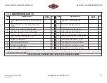
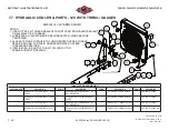
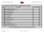
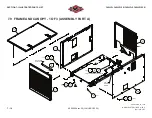
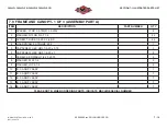
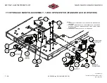
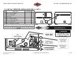
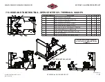
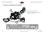
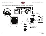
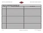
7.11 HYDRAULIC MANIFOLD ASSEMBLY - CLOSED CENTER 24V (STANDARD & COLD WEATHER)
ITEM
DESCRIPTION
VANAIR PART
NUMBER
IMT PART
NUMBER
QTY
1
CONNECTOR, #4 MSAE x #4 MJIC
260387-103
1
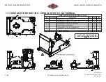
2
CONNECTOR, #16 MSAE x #8 MJIC
260387-118
1
3
CONNECTOR, #16 MSAE x #12 MJIC
260387-119
1
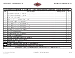
4
BULKHEAD, 1 1/16 - 12UNF x 1 5/16 - UNF
269751
1
5
VALVE, HYD ASSY CLOSE CENTER 24V
277854
1
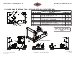
6
CAP, FEMALE JIC SHIPPING #4 7/16-20
279109-001
1
7
CAP, FEMALE JIC SHIPPING #6 9/16-18
279109-002
1
8
CAP, FEMALE JIC SHIPPING #12 1 1/16-12
279109-005
1
9
CAP, FEMALE JIC SHIPPING #16 1 5/16-12
279109-006
1
10
BRACKET, HYD OIL CLSD CTR MNFLD
279469
1
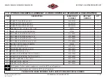
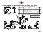
11
NUT, HEX LOCKING 5/16-18
825505-166
2
12
CAPSCREW, HEX GR5 5/16-18 x 2.75
829105-275
2
13
SCREW, SER WASH 5/16-18 x 1
829705-100
2
14
WASHER, LOCK INTERNAL TOOTH 7/16 INCH
837407-040
1
15
WASHER, LOCK INTERNAL TOOTH 9/16 INCH
837409-045
1
16
WASHER, INTERNAL TOOTH 1 INCH
837414-100
1
17
BULKHEAD, MJIC x MJIC #4
862104-025
1
18
BULKHEAD, MJIC x MJIC #6
862106-038
1
A
Flow Regulator: For
fl
ow regulator replacement, consult the IMT Service Department.
B
Solenoid: For solenoid replacement, consult the IMT Service Department.
PLEASE NOTE: WHEN ORDERING PARTS, INDICATE MACHINE SERIAL NUMBER.
Содержание CAS40PL
Страница 2: ...BLANK PAGE...
Страница 81: ...BLANK PAGE...


