


99906549 rev 00 (JANUARY-2020)
5 - 11
SECTION 5: MAINTENANCE
IOWA MOLD TOOLING CO., INC.
(641) 923-3711
CAS40PL, CAS40PL-CW, CAS40PLE, CAS40PLE-CW
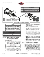
2. Position hub on mating shaft. Ideal hub po-
sition is with the pocket face of the hub
fl
ush
with the end of mating shaft. Overhung hubs
should have a minimum shaft engagement
equal to the hub bore diameter.
3. With hub properly positioned, torque clamp-
ing fastener to recommended seating torque.
The manufacturer recommends using me-
dium strength removable Loctite for bore &
key way setscrew (see
Figure 5-6
for proper
bore & key way setscrew seating torques).
4. Repeat steps #2 and #3 for the driven shaft
hub.
5. Move driven and driving equipment togeth-
er until proper distance between hubs is
achieved (assembly gap can be used as
reference when unable to measure distance
between hubs. See
Figure 5-6
for proper dis-
tance between hubs and assembly gap).
6. Ensure driven unit is aligned to driving unit,
within couplings allowable misalignment.
ANGULAR ALIGNMENT
Measure the assembly gap between hubs in
(4) locations 90° apart the measurement range
should not exceed the angular limit listed in
Fig-
ure 5-6
.
PARALLEL ALIGNMENT
Place a straight edge square on the outer diam-
eter of both hubs in (4) locations 90° apart; the
maximum gap should not exceed the o
ff
set limit
listed in
Figure 5-6
.
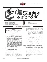
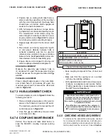
5.4.7.3 HUB ALIGNMENT CHECK
To ensure alignment, refer to
Figure 5-6
and the
following procedure:
1. Place a straight edge square on the outer di-
ameter of both halves in locations 90° apart.
The maximum gap should not exceed the o
ff
-
set limit as given in
Figure 5-6
.
2. Once this gap is satisfactory, torque screws
to 14 ft-lbs (19.0 Nm).
5.4.7.4 COUPLING MAINTENANCE
Perform the checks and tasks listed below to
keep the CAS40PL coupling in proper working
order.
A
B
KEY
DESCRIPTION
A
DISTANCE BETWEEN HUBS: 0.945 inches
B
ASSEMBLY GAP: 0.118 inches
OFFSET LIMIT: 0.009 inches
ANGULAR LIMIT: 0.030 inches
Figure 5-6: Hub Alignment Check
• Keep coupling components free of dust and
dirt.
• Make sure that the coupling is not in contact
with any non-rotating surfaces.
• Verify application data and review torque spec-
i
fi
cations, mis-alignment and service factors.
If further assistance is needed please contact
the IMT
®
Service Department.
IMPORTANT
Hubs that are modi
fi
ed or machined by the
customer are not covered under the standard
warranty terms. Any modi
fi
cations to instruc-
tions and/or coupling characteristics may result
in a premature failure.
If modi
fi
cations are made by the customer, it
is recommended that the customer adheres to
IMT’s machining standards to ensure proper
operation.
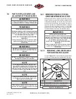
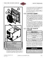
5.4.8 CHECKING HOSES AND WIRING
To maximize the accessible work space needed
for compressor unit maintenance, both side pan-
els (drive assembly access panel and instrumen-
tation panel) must be removed. Consult
Section
Содержание CAS40PL
Страница 2: ...BLANK PAGE...
Страница 81: ...BLANK PAGE...


