


30
IMT CAS2545 Air Compressor Manual Part No. 99904145
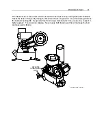
Description of Components
COMPRESSOR ASSEMBLY
The IMT compressor assembly is a positive displacement, oil flooded, rotary screw type unit
employing one stage of compression to achieve the desired pressure. Components include a
housing (stator), two screws (rotors), bearings, and bearing supports. Power from the hydraulic
motor is transferred to the male rotor through a belt and pulley configuration. The female rotor is
driven by the male rotor. There are four lobes on the male rotor and five roots on the female
rotor.
PRINCIPLES OF OPERATION
In operation, two helical grooved rotors mesh to compress air. Inlet air is trapped as the male
lobes roll down the female grooves, pushing trapped air along, compressing it until it reaches the
discharge port in the end of the stator and delivers smooth-flowing, pulse-free air to the receiver.
During the compression cycle, oil is injected into the compressor. The oil lubricates the rotating
parts and bearings; serves as a cooling agent for the compressed air; and seals the running
clearances.
LUBRICATION SYSTEM
Oil from the compressor oil sump, at compressor discharge pressure, is directed through the oil
filter, cooling system, and to the side of the compressor stator, where it is injected into the
compressor. At the same time oil is directed internally to the bearings and shaft seal of the
compressor. The oil-laden air is then discharged back into the sump.
OIL SUMP
Compressed, oil-laden air enters the sump from the compressor. As the oil-laden air enters the
sump, most of the oil is separated from the air as it passes through a series of baffles and
diffusion plates. The oil accumulates at the bottom of the sump for recirculation. However,
some small droplets of oil remain suspended in the air and are passed on to the coalescer.
PRESSURE RELIEF VALVE
The pressure relief valve is set at 210 psi
.
It is located at the top of the air/oil sump. This valve
acts as a backup to protect the system from excessive pressure that might result from a
malfunction.
AIR/OIL COALESCER
The coalescer is self-contained within the air end assembly. When air is demanded at the
service line, it passes through the coalescer which efficiently provides the final stage of oil
separation.
Содержание CAS2545
Страница 2: ......
Страница 6: ......
Страница 11: ...Section 1 Compressor Introduction 9 Warning Caution Decals WARNING Do not operate with cover removed...
Страница 15: ...Section 1 Compressor Introduction 13 CAS2545 Performance Charts...
Страница 16: ...14 IMT CAS2545 Air Compressor Manual Part No 99904145...
Страница 17: ...Section 1 Compressor Introduction 15...
Страница 38: ......
Страница 54: ......
Страница 71: ...Parts 69 Electrical Schematic 77441156...
Страница 72: ...70 IMT CAS2545 Air Compressor Manual Part No 99904145 Hydraulic Schematic 99904155...


