


Printed on 19 February, 2007
Manual Part No. 99904145
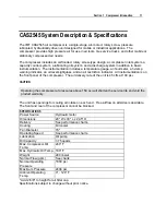
IMT CAS2545 Air Compressor
Operation, Maintenance and Spare Parts
Revised 20070220
IOWA MOLD TOOLING CO., INC.
PO Box 189
Garner, IA 50438
Tel: 641-923-3711 FAX: 641-923-2424
Website: http://www.imt.com
Copyright © 2007 Iowa Mold Tooling Co., Inc.
All rights reserved
No part of this publication may be reproduced, stored in a retrieval system, or transmitted in any
form or by any means, electronic, mechanical, photocopying, recording or otherwise without the
prior written permission of Iowa Mold Tooling Co., Inc.
Iowa Mold Tooling Co., Inc. is an Oshkosh Truck Corporation Company.
Содержание CAS2545
Страница 2: ......
Страница 6: ......
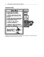
Страница 11: ...Section 1 Compressor Introduction 9 Warning Caution Decals WARNING Do not operate with cover removed...
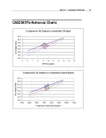
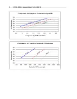
Страница 15: ...Section 1 Compressor Introduction 13 CAS2545 Performance Charts...
Страница 16: ...14 IMT CAS2545 Air Compressor Manual Part No 99904145...
Страница 17: ...Section 1 Compressor Introduction 15...
Страница 38: ......
Страница 54: ......
Страница 71: ...Parts 69 Electrical Schematic 77441156...
Страница 72: ...70 IMT CAS2545 Air Compressor Manual Part No 99904145 Hydraulic Schematic 99904155...