background image

Cheetah Pregius Camera with Camera Link 

 User Manual


July 6, 2018 

Page 

64 

of

 64


Rev 1.1


Address 

Register Name 

Data 

Type 

Usage 

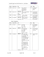
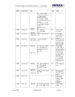
0x0F 

 Frame Pulse 

Data (31:8) 

N/A 


Miscellaneous Registers 

Address 

Register Name 

Data 

Type 

Usage 

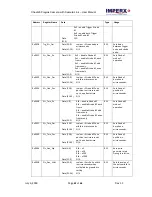
0x0604 

Baud_rate_sel 

Data (2:0) 

0x0 

 9600 

0x1 

 19200 

0x2 

 38400 

0x3 

 57600 

0x4 

 115200 (default) 

0x5 to 0x7 - reserved 

Data (31:3) 

N/A 


RW 

RS-232 Baud Rate 
Selector 0=9600, 
1=19200, 
2=38400, 3=57600 
and 4=115200 bps 

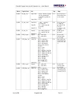
0x060C 

RGS_ID#_Register 


RW 

Contains RGS ID 
number register. 


Содержание Cheetah C2020

Страница 1: ... and C4120 CMOS cameras provide exceptional video image quality in a remarkably compact and ruggedized design The cameras use Sony Pregius CMOS sensors for their high sensitivity image clarity and high dynamic range They achieve frame rates up to 148 frames per second with Camera Link Full PoCL output Revision 1 1 ...

Страница 2: ...ications including flat panel inspection biometrics aerial mapping surveillance traffic management semiconductors and electronics scientific medical Imaging printing homeland security space exploration and other imaging and machine vision applications Fortune 100 companies federal and state government agencies domestic and foreign defense agencies academic institutions and other customers worldwid...

Страница 3: ... by IMPERX for its use IMPERX reserves the right to make changes to this information without notice Redistribution of this manual in whole or in part by any means is prohibited without obtaining prior permission from IMPERX IMPERX reserves the right to make changes to its products or to discontinue any product or service without notice and advises its customers to obtain the latest version of rele...

Страница 4: ...Electrical Connectivity 16 2 3 Mechanicals 18 2 4 Optical 21 2 5 Environmental 21 3 Configuration Software 22 3 1 Overview 22 3 2 Installing the Software 22 Installation 22 3 3 Starting CamConfig 26 3 4 Main Window 26 3 4 1 Menu 27 3 4 2 View 30 3 4 3 Help 30 3 5 Gain Exposure 30 3 6 Output 32 Output OUT1 and OUT2 33 Strobes 1 and 2 33 Pulse Generator 34 3 7 Trigger Control 35 3 7 1 Trigger Option...

Страница 5: ...46 4 7 Color Control 47 4 8 Image Sensor Technology 47 4 9 Micro polarized Camera 48 5 Register based Commands 49 5 1 Configuration Memory 49 5 1 1 Camera Serial Protocol 49 Appendix A Camera Registers 53 A 1 Camera Register Structure 53 Local Space 53 Boot Loader 54 Camera Info Registers 54 EEPROM Space 55 Factory User1 User2 User3 User4 FLASH Store 55 Sony IMX xxx Registers 55 Data 1 Registers 5...

Страница 6: ... Manual July 6 2018 Page 6 of 64 Rev 1 1 REVISION HISTORY Revision Date Reviser Comments 1 0 12 21 2017 R Johnston Initial release 1 1 07 06 2018 R Johnston Added AEC AGC speed control added C2420 polarizer camera updated Image Control GUI screen ...

Страница 7: ...2LLR CLF C2020C 3 2048 x 1536 148 Color 1 1 8 Sony IMX 252LQR CLF C2420M 5 2448 x 2048 97 Mono 2 3 Sony IMX 250LLR CLF C2420C 5 2448 x 2048 97 Color 2 3 Sony IMX 250LQR CLF C2420Z 5 2462 x 2056 97 Mono 2 3 Sony IMX 250MZR CLF C4020M 9 4096 x 2160 57 Mono 1 Sony IMX 255LLR CLF C4020C 9 4096 x 2160 57 Color 1 Sony IMX 255LQR CLF C4120M 12 4096 x 3000 42 Mono 1 1 Sony IMX 253LLR CLF C4120C 12 4096 x ...

Страница 8: ... Specifications C2020 3 1 MP C2420 5 MP Active image resolution 2064 H x 1544 V 2464 H x 2056 V Pixel size 3 45 μm 3 45 μm Optical format 1 1 8 inch 2 3 inch Shutter Global Global Frame rate max 148 8 bit 121 10 bit 54 12 bit 97 8 bit 79 10 bit 35 12 bit Digitization 8 bit 10 bit 12 bit 8 bit 10 bit 12 bit Pixel Clock rate 37 125MHz 37 125MHz Dynamic range 71 dB 71 dB Shutter speed 1 µs step 14 µs...

Страница 9: ... inrush 12VDC 5V 30V 1 5 A inrush Power Typical 200mA 12V Typical 200mA 12V Camera size W x H x L 37mm W 37mm H 48 6mm L 37mm W 37mm H 48 6mm L Weight 91 8 grams 91 8 grams Vibration shock TBD TBD Environmental 40 C to 85 C Operating 50 C to 90 C Storage 40 C to 85 C Operating 50 C to 90 C Storage Relative humidity 10 to 90 non condensing 10 to 90 non condensing Regulatory FCC 15 part A CE RoHS FC...

Страница 10: ...inrush Power Typical 200mA 12V Camera size W x H x L 37mm W 37mm H 48 6mm L Weight 91 8 grams Vibration shock TBD Environmental 40 C to 85 C Operating 50 C to 90 C Storage Relative humidity 10 to 90 non condensing Regulatory FCC part 15 CE RoHS 1 2 3 C4020 and C4120 Cameras Specifications C4020 9 MP C4120 12 MP Active image resolution 4112 H x 2176 V 4112 H x 3008 V Pixel size 3 45 μm 3 45 μm Opti...

Страница 11: ...0 2 lux f 1 4 0 2 lux f 1 4 Lens mount C mount default C mount default Test image patterns Yes Yes In camera processing Yes Yes Camera housing 6000 series aluminum 6000 series aluminum Upgradeable firmware Yes Yes Data correction 4 LUTs 1 LUT pre programmed with Gamma 0 45 bad pixel correction 4 LUTs 1 LUT pre programmed with Gamma 0 45 bad pixel correction Supply voltage range 12VDC 5V 30V 1 5 A ...

Страница 12: ... camera is fully tested before shipping If for some reason the camera is not operational after power up check the following 1 Check the power supply and all I O cables Make sure that all the connectors are firmly attached 2 Check the status LED and verify that it is steady ON if not refer to the LED section 3 Enable the test mode and verify that the communication between the frame grabber and the ...

Страница 13: ...niature locking receptacle HR10A 10R 12PB 71 providing power and I O interface 3 Status LED indicating the status of the camera 2 1 2 Camera LED Status 4 Model Serial Number showing the camera model and serial number 2 1 1 Pin Assignments The Hirose connector on the camera s back panel is a male type miniature locking receptacle HR10A 10R 12PB 71 The Imperx power supply sold separately terminates ...

Страница 14: ...ondition Status Indication Green steady ON Normal operation You should see a normal image coming out of the camera Green blinks at 2 0 Hz Programmable Frame Time enabled Amber steady ON Test mode You should see one of the test patterns Amber blinks at 0 5 Hz Camera is in AGC AEC mode or trigger mode In this AGC AEC mode changing the shutter slider does not affect image luminance Red steady ON RS 2...

Страница 15: ...Output 12V 1 5m 5 15cm 6 connector HIROSE HR10A 10P 12S Strobe Trigger 15cm 6 1cm 0 5 connector BNC male Auto Iris Option 15cm 6 1cm 0 5 Video type 4 Pin MINI plug connector E4 191J Electrical Over Voltage Protective Installation Short circuit Protective Installation Protection Type Auto Recovery 12V to 13 VDC 12 6VDC nominal 2 A Load regulation 5 Ripple Noise 1 Max Regulatory Class 1 Safety stand...

Страница 16: ...ternal output electrical connections A Input IN 1 Opto Isolated Input signals IN1 and IN1 Rtn are optically isolated and the voltage difference between the two must be positive between 3 3 and 24 volts Figure 4 IN1 electrical connection B Input IN 2 LVTTL Input signals IN2 and IN2 Rtn provide interfaces to a TTL or LVTTL input signal The signal level voltage difference between the inputs IN2 and I...

Страница 17: ...d switch There is no pull up voltage on either contact External pull up voltage of up to 25 volts is required for operation Output is not polarity sensitive AC or DC loads are possible The voltage across OUT2 Contact 1 and OUT2 Contact 2 must not exceed 25 volts and the current through the switch must not exceed 50 mA On resistance is less than 5 Ohms Figure 7 Open drain logic driver Figure 8 Low ...

Страница 18: ...ined aluminum For maximum flexibility the camera has eight M3X0 5mm mounting holes located towards the front of the camera on all four sides An additional plate with 20 UNC tripod mount and hardware ship with each camera Figure 10 C2020 C2420 C2420Z C4020 C4120 camera The following mechanical drawings show side front and back views of the C2020 C2420 C2420Z C4020 C4120 cameras ...

Страница 19: ...Cheetah Pregius Camera with Camera Link User Manual July 6 2018 Page 19 of 64 Rev 1 1 Figure 11 Mechanical drawing side view Figure 12 Mechanical drawing image plane side view ...

Страница 20: ...Cheetah Pregius Camera with Camera Link User Manual July 6 2018 Page 20 of 64 Rev 1 1 Figure 13 Mechanical drawing back view Figure 14 Mechanical drawing front view ...

Страница 21: ...ckness or less inserted under the front lens bezel 1 Avoid direct exposure to a high intensity light source such as a laser beam This may damage the camera optical sensor 2 Avoid foreign particles on the surface of the imager 2 5 Environmental Operate the camera in a dry environment with temperatures between 40 C and 85 C Relative humidity should not exceed 80 non condensing Always keep the camera...

Страница 22: ...nd 64 bit Windows 10 32 bit and 64 bit 3 2 Installing the Software Use the installation wizard to install the Cheetah Pregius CamConfig software supplied with your camera If a previous version of the GUI software is installed on your computer you must remove it before completing the installation The installation wizard will do this for you during the installation process Or you can uninstall a pre...

Страница 23: ...ius_1_0_5_xxxx exe on your desktop The Welcome Setup screen opens Note the recommendation to close other applications and then click Next 2 When the License Agreement screen appears read the agreement and click I Agree 3 On the Choose Components screen make sure the Cheetah Pregius CamConfig component is selected and then click Next ...

Страница 24: ...1 1 4 On the Choose Install Location screen accept the default destination folder or click Browse and select a different location and then click Install The installer prompts you to uninstall any existing versions of the software from your computer before continuing the installation ...

Страница 25: ...ion Complete screen select the check box to register your software and then click Next When the Imperx website appears complete the Subscriber Registration and click Submit 6 On the Completing Cheetah Pregius CamConfig Setup screen click Finish The Cheetah Pregius Configurator icon appears on your desktop ...

Страница 26: ...by clicking Rescan Ports If the software does not find your computer s COM ports you might need to locate your frame grabber s DLL file and move it to C Windows System32 You can search File Explorer for the DLL file by entering clser in the search field Note your frame grabber s vendor name abbreviation should appear where XXX is shown in the clserXXX dll file name To select a camera for programmi...

Страница 27: ...mplement The software monitors the image size in pixels frame per second FPS frame time in milliseconds FTM and exposure time in milliseconds EXP 3 4 1 Menu The Menu provides access to load options settings the command terminal and more Figure 17 Menu options Run Application This starts any other executable file that you normally use such as a frame grabber application CamConfig remembers the loca...

Страница 28: ...n from User Space 1 2 3 or 4 upon powering up Command Terminal The Command Terminal shows information about all commands sent to or received by the camera It also lets you communicate directly with the camera by entering write or read commands directly into the text box on the Command Terminal screen To write a command to a camera register the command terminal must send a sequence of 7 bytes to th...

Страница 29: ...g check box Download Terminal The Download Terminal lets you upgrade the camera s firmware and upload any custom files BPM Flat Field Correction FFC Lookup Tables LUT or Register Set RGS Figure 19 Download Terminal To download files to the camera 1 Click File Type and select a file type such as BPM or LUT1 LUT2 2 Enter or browse to the location of the file on your computer 3 Select the file you wa...

Страница 30: ... Strobe Processing Color and Data Out on the screen 3 4 3 Help Help provides access to a user help file and the following options Debug This puts the software in debug mode for test purposes and troubleshooting Save Dump Camera Regs This is for saving camera registers to a file About This provides information about the camera s firmware build revision image sensor and other components 3 5 Gain Exp...

Страница 31: ...amic range without black level clipping for short exposures and 10 to 15 for long exposures Exposure Mode Use the following to set the camera exposure Off Sets the exposure time equal to the frame period Pulse Width Sets the exposure time equal to the trigger s input pulse width Internal Sets the internal camera timer control exposure based on the Exposure Time setting Use the slider to adjust the...

Страница 32: ...Camera Link User Manual July 6 2018 Page 32 of 64 Rev 1 1 Figure 24 Line time settings 3 6 Output Output Control lets you configure the camera for the two strobe outputs trigger signal and pulse generator Figure 25 Output Control ...

Страница 33: ...esents the even frame odd is low Trigger Pulse Maps the input trigger pulse to the output with no delay as is Trigger Pulse Delayed Maps the input trigger pulse to the output with delay set by the Exposure Delay Register Camera Ready A signal indicating when the camera is ready to accept the next trigger pulse Pulse Generator Maps the internal pulse generator waveform to the output Strobe 1 Maps t...

Страница 34: ...tive pulses Width Sets the amount of time in microseconds determined by the granularity setting the pulse remains at a high level before falling to a low level Delay Shows the delay calculated in microseconds as Period minus Width Frequency Shows the frequency calculated as 1 Period Number of Pulses Enables sending pulses either continuously or by a set number of pulses Two modes are available Con...

Страница 35: ...e of the following active triggering input signals from the drop down list External 1 The camera expects a trigger signal coming from IN 1 Pulse Gen The camera expects a trigger signal coming from the internal pulse generator Computer The camera expects a signal coming from CC 1 Software Triggering starts when you click the software trigger button External 2 The camera expects a trigger signal com...

Страница 36: ...trigger pulse active edge and beginning of the exposure You can set the delay from 0 to 16777215 microseconds Frames per trigger When the Mode is Standard this option lets you select the number of frames to capture expose and read out per trigger Select from 1 to 65530 or CONT continuous frames Trigger Strobe Options The camera can send a strobe pulse to synchronize the camera to an external light...

Страница 37: ...hat value to the value entered in the Limit field to determine changes to the exposure gain settings Exposure Limits Enter a minimum and a maximum limit For example if motion capture is important specify a short maximum exposure to avoid motion blur Exposure Limits range from 25 microseconds to a maximum limit of one frame time Generally the minimum exposure limit should be set to a minimum of 30 ...

Страница 38: ... Interest SAOI binning polarization image structure image correction and test mode Figure 29 Image Control The AOI affects the camera s frame rates The following table shows C2020 frame rates based on various AOI s Product AOI FPS C2020 2064 x 1544 149 2064 x 514 426 2064 x 255 802 2064 x 128 1412 2064 x 64 2302 2064 x 32 3339 2064 x 16 4310 2064 x 8 5025 2064 x 4 5494 516 x 4 5494 256 x 4 5494 17...

Страница 39: ...omatic gain control AGC automatic exposure control AEC auto white balance AWB or LUT Mode A drop down lets you select the following SOAI modes Slave AOI Modes Descriptions Off Turns off all modes Include Displays the Master AOI image with the Slave AOI image included the area outside of the Slave AOI appears black Exclude Displays the Master AOI with the Slave AOI excluded the Slave AIO appears bl...

Страница 40: ... want to change the CMOS A D Bits settings use the following procedure 1 Turn off Binning and AOI 2 Set Binning by clicking 2x for both horizontal and vertical 3 Set the AOI horizontal and vertical sizes 4 Select a new CMOS A D Bits Options are 8 bits 10 bits or 12 bits 3 9 5 Polarization Mode C2420Z Camera Polarization mode activates the polarization capabilities of the C2420Z camera The camera s...

Страница 41: ...of bit positions positions are 1x 2x 3x up to 7x CL Out Bits Sets the number of bits per pixel output to the Camera Link output Options are 8 10 and 12 bits CL Output Format Sets the number of Camera Link output taps used Options are Base 2 taps Medium 4 taps and Full 8 taps Camera Link cameras require a frame grabber device on the computer for capturing individual frames from the camera s video s...

Страница 42: ...rrection maps Dynamic User Combines dynamic pixel correction and use of factory bad pixel maps Correction Depth For Dynamic Pixel Correction you can set a threshold level from 0 to 4095 for 12 bit images The camera will correct all hot pixels having an amplitude hot pixel intensity minus average pixel intensity higher than the threshold setting FFC Activates a flat field correction table created b...

Страница 43: ...output H Ramp A stationary horizontal ramp image V Ramp A stationary vertical ramp image H V Ramp A pair of horizontal and or vertical lines positioned in the image at any pixel line in the image You can use the horizontal and vertical lines as a measuring tool the pixel and line positions are referenced to the CCD pixels and lines not to the image pixels and lines H V Ramp Moving A moving horizon...

Страница 44: ...uses the correction coefficients as entered from the user Table 4 White balance presets Use Manual WB Coefficients to manually define white balance coefficients for each color red green and blue Coefficient values affect the intensity of each color and range from 0 to 4095 The Statistic area of the screen gives you the current calculated white balance coefficients per color For best color accuracy...

Страница 45: ...e to be either the average luminance or peak luminance within the image or within the AOI The camera adjusts the exposure starting within the preset limit established by the user specified minimum maximum limits When AEC and AGC are enabled exposure is always varied first until the exposure reaches the maximum limit The camera then indicates the limit has been reached and begins increasing the gai...

Страница 46: ...art middle or end of exposure or the start of image readout 1 The Trigger Strobe feature creates a strobe output signal from the trigger input signal The strobe can be delayed with respect to trigger using the Trigger Strobe delay feature see Trigger Control Trigger Strobe Options 2 The camera provides signals indicating the start of exposure mid exposure and end of exposure see Output Control Out...

Страница 47: ...ries with the wavelength of the incident light When the camera reaches the desired exposure time it shifts the charges from each pixel photodiode onto a storage register within the pixel reads out one row at a time and then digitizes each pixel at either 8 10 or12 bits as selected by the user Frame time or read out time is the time interval required for all the pixels to be read out of the image s...

Страница 48: ...n block certain light waves from reaching the image sensor and thereby improve image quality The Sony IMX 250MZR image sensor in the Cheetah C2420Z camera includes a micro polarizer filter that blocks light waves based on a polarization angle The filter consists of an array of four polarizers grouped in a 2x2 sub array As shown in the following illustration each array covers a block of four pixels...

Страница 49: ... Flash based The camera allows you to save the contents of the workspace to either one of these memory spaces and allows you to load these contents into the workspace In this way you can easily save and restore up to four different camera configurations Upon powering up the camera the firmware loads the work space registers from the factory space and user space 1 user space 2 user space 3 and user...

Страница 50: ...nd response length 5 1 1 1 Write Operation To write to any given camera register send a sequence of 7 bytes to the camera If there is no error the camera returns a one byte acknowledge for the write command Ack Write to camera 7 Bytes Write_Cmd Address Data 1st byte 0x57 Write Command 2nd byte Register Address_High MSB 3rd byte Register Address_Low LSB 4th byte Register Data Byte 4 MSB 5th byte Re...

Страница 51: ... read command Ack and four bytes of data DD DD DD DD During read operation the camera does not return an error or Nac The only exception is the case of invalid command shown in the Normal read cycle diagram below If you specify a wrong address the camera returns acknowledge 06 and four bytes of data 00 00 00 00 Read from camera 3 Bytes Read_Cmd Address 1st byte 0x52 Read Command 2nd byte Register ...

Страница 52: ...ster data payload value 0x11223344 Register data 0x06 11 22 33 44 5 1 1 3 Error Code Description To manage camera reliability use the following not acknowledge error codes x00 No error x01 Invalid command An invalid command not 52 or 57 sent to the camera x02 Time out x03 Checksum error x04 Value less than minimum x05 Value higher than maximum x06 AGC error x07 Supervisor mode error x08 Mode not s...

Страница 53: ...egisters user command FW info and all camera status registers 2 Camera Manufacturing Space starting address 0x7000 This space contains all camera manufacturing information Writing to the Manufacturing space is allowed only when the Supervisory mode is enabled 3 Camera EEPROM starting address 0x5000 This space contains the Boot From settings 4 Camera Factory Space This space contains all camera reg...

Страница 54: ... Load WO Commands camera to load workspace from selected space 0x6060 0x6068 User Set Save WO Commands camera to load workspace from selected space 0x6060 Camera Info Registers Address Register Name Data Type Usage 0x6070 Hor_Frm_Range Data 15 0 Min Horizontal Size Data 31 16 Max Horizontal Size RO Returns min max horizontal image frame size in pixels 0x6074 Ver_Frm_Range Data 15 0 Min Vertical Si...

Страница 55: ...ge luminance during normal and AGC operation EEPROM Space Address Register Name Data Type Usage 0x5000 Boot User Set Default Selector Data 2 0 0x0 Boot from Factory 0x1 Boot from User 1 0x1 Boot from User 2 0x1 Boot from User 3 0x1 Boot from User 4 0x5 or 0x7 reserved Data 31 3 RW Determines configuration space factory user 1 user 4 to load in camera after a power cycle or reset SW_Reset command F...

Страница 56: ...ertical Decimation disable 0x1 Vertical Decimation enable Data 31 1 N A RW Sets Vertical Subsampling 2 1 0x002C Ver_Bin_En Data 0 0x0 No Vertical Binning 0x1 2x Vertical Binning Data 31 1 N A RW Vertical Binning 2 1 Mode Enable 0x0030 Img_Hrev_en Data 0 0x0 Horizontal Flip Disable 0x1 Horizontal Flip enable Data 31 1 N A RW Flips image left to right 0x0034 Img_Vrev_en Data 0 0x0 Vertical Flip Disa...

Страница 57: ...it max in microseconds Data 1 Registers Address Register Name Data Type Usage 0x0100 Bit_Dpt_Sel Data 1 0 0x0 8 bit 0x1 10 bit 0x2 12 bit 0x3 reserved Data 31 2 N A RW Selects bit depth transmitted over Camera Link output 0x0104 Dat_Fmt_Sel Data 2 0 0x0 Base 2 taps 0x1 Base 3 taps 0x2 Medium 0x3 Full 0x4 DECA 0x5 to 0x7 reserved Data 31 3 N A RW Selects tap format for the CL camera data output 0x0...

Страница 58: ...on BPC 0x0120 Dyn_BPC_Thld Data 11 0 value Threshold value Data 31 2 N A RW Sets Dynamic Pixel Correction DPC threshold 0x0124 FFC_En Data 1 0 0x0 FFC disable 0x1 FFC 1 enable 0x2 FFC 2 enable Data 31 2 N A RW Enables Flat Field Correction FFC 0x0128 Neg_Img_En Data 0 0x0 Positive image 0x1 Negative image Data 31 1 N A RW Enables negative image 0x012C Aoi_Slv1_En Data 2 0 0x0 SAOI disable 0x1 SAOI...

Страница 59: ... 31 1 N A RW Enables Auto Gain Control AGC 0x0148 Agc_Lum_Lev Data 11 0 value desired luminance level Data 31 12 N A RW Provides AGC luminance level control 0x014C Avg_Peak_Sel Data 1 0 0x0 average luminance 0x1 peak luminance 0x2 or 0x3 reserved Data 31 2 N A RW Sets luminance mode during AEC or AGC process 0x0150 Agc_Agn_Min Data 8 0 value minimum AGC gain limit Data 31 9 N A RW Sets AGC Gain Lo...

Страница 60: ... 0x0208 WB_Green Data 11 0 value WB Green coefficient Data 31 12 N A RW Contains the white balance correction coefficients for Green In manual mode user enters the coefficients 0x020C WB_Blue Data 11 0 value WB Blue coefficient Data 31 12 N A RW Contains the white balance correction coefficients for Blue In manual mode user enters the coefficients I O Interface Registers Address Register Name Data...

Страница 61: ...ds Any pulse shorter than the selected time is ignored 0x0514 Trg_Ovr_Sel Data 1 0 0x0 ignore next trigger 0x1 accept only after exposure is completed 0x2 N A 0x3 N A Data 31 2 N A RW Selects trigger overlap mode If camera receives a trigger pulse while still processing previous trigger user has option to ignore the incoming trigger or to terminate previous process and start a new one 0x0518 Trg_M...

Страница 62: ...ue Strobe 1 Pulse position in microseconds up to one frame time Data 31 24 N A RW Sets Strobe 1 position in microseconds 0x0538 Str_Two_En Data 1 0 0x0 disable Strobe 2 0x1 enable Strobe 2 each frame 0x2 enable Strobe 2 odd frames only 0x3 enable Strobe 2 even frames only Data 31 2 N A RW Sets Strobe 2 mode of operation 0x053C Str_Two_Dur Data 15 0 value Strobe 2 Pulse width in microseconds Data 3...

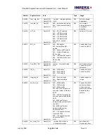
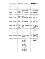
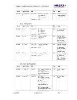
Страница 63: ... active Low or High 0x055C OUT1_Map_Sel Data 7 0 0x00 no mapping 0x01 exposure start 0x02 exposure end 0x03 mid exposure 0x04 active exposure window 0x05 H sync 0x06 V sync 0x07 odd even frame flag 0x08 trigger pulse actual 0x09 trigger pulse delayed 0x0A camera ready 0x0B pulse generator 0x0C strobe 1 0x0D strobe 2 0x0E toggle OUT 1 0x0F Frame pulse Data 31 8 N A RW Maps the various internal sign...

Страница 64: ...ulse Data 31 8 N A Miscellaneous Registers Address Register Name Data Type Usage 0x0604 Baud_rate_sel Data 2 0 0x0 9600 0x1 19200 0x2 38400 0x3 57600 0x4 115200 default 0x5 to 0x7 reserved Data 31 3 N A RW RS 232 Baud Rate Selector 0 9600 1 19200 2 38400 3 57600 and 4 115200 bps 0x060C RGS_ID _Register RW Contains RGS ID number register ...

Отзывы: