47
7.3 Digital Inputs
NOTE:
The digital inputs on the I3N are designed for low-voltage DC inputs
.
The inputs are designed to
support both positive and negative input modes. The mode is set by a configuration parameter in I3
configurator. All the inputs on the unit must be configured to the same mode.
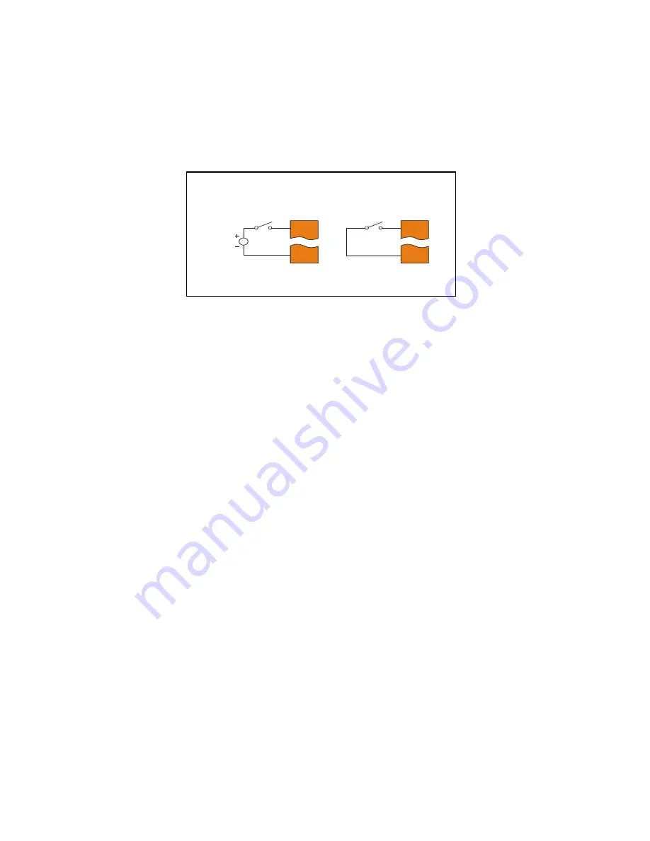
Figure 7.1 – Positive and Negative Inputs
In positive logic mode a positive voltage applied to the input will turn the input. The internal design of this
mode is basically a resistor from the input to I/O ground. This mode is sometimes called sourcing.
In negative logic mode, connecting the input to the I/O ground or 0V will turn the input on. The internal
design of this mode is basically a resistor from the input to the positive I/O voltage (usually 12 or 24V).
This mode is sometimes called sinking.
I1
0V
001XLE036
12-24VDC
I1
0V
Positive Logic In Negative Logic In
Positive Logic vs. Negative Logic Wiring
The RCC SERIES CONTROLLER can be wired for Positive Logic
inputs or Negative Logic inputs.
Содержание i3N Series
Страница 1: ...Think inside the box User Manual For i3 N Series Controllers...
Страница 39: ...39...


