


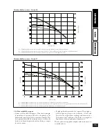


• External temperature sensor. is sensor can be connected
directly to the boiler electrical system and allows the max.
system delivery temperature to be automatically decreased
when the outside temperature increases, in order to adjust
the heat supplied to the system according to the change
in the outside temperature. e external sensor always
operates when connected, regardless of the presence or
type of room chronothermostat used, and can work in
combination with both Immergas chronothermostats.
e correlation between system delivery temperature and
outside temperature is determined by the position of the
knob on the boiler control panel according to the curves
shown in the diagram. e external sensor electrical con-
nection must be made to terminals 38 and 39 on the boiler
electronic card (see fig. page 5).
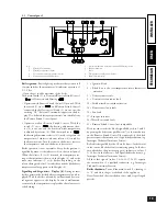
Electrical connection of the Remote Friend Control or
On/Off chronothermostat (Optional).
The following
operations must be carried out after disconnecting the
electrical power supply; the possible thermostat or On/Off
room chronothermostat must be connected to terminals 40
and 41 eliminating jumper X20 (see fig. page 5). Make sure
the On/Off thermostat contact is of the “clean” type, i.e.
separate from the mains supply, otherwise the electronic
adjustment card would be damaged. e possible Remote
Friend Control must be connected by means of terminals
IN+ and IN- to terminals 42 and 43 on the electronic card
(in the boiler) respecting the polarity, (see fig. page 5);
connection with the wrong polarity inhibits its operation,
but without damaging the Remote Friend Control. After
connecting to the Remote Friend Control, jumper X20 must
be eliminated. e boiler works with the parameters set on
the Remote Friend Control only if the boiler main switch is
turned to Domestic/Remote Friend Control (
).
Important:
If the Remote Friend Control is used arrange
two separate lines in compliance with current regulations
regarding electrical systems. Boiler pipes must never be used
to earth the electrical or telephone system. Ensure this does
not occur, before making the boiler electrical connections.
Installation with system operating at low temperature.
e boiler can directly feed a low temperature system, by
operating on jumper (5) and setting the delivery temperature
range from 45°-25°C (as described on page 27). In this mode
it is advisable to include a safety in series with the boiler
circulating pump, formed of a thermostat having a limit
temperature of 55 °C. e thermostat must be positioned
on the system delivery pipe at more than 2 metres from the
boiler.
1.4 Boiler installation - B
23
type with open chamber
and forced draught (optional).
In this configuration it is necessary to use the special terminal
(included in the special intake kit) to be fitted on the intake
hole on the sealed chamber (see the following fig.). Air is
drawn directly from the place where the boiler is installed,
and fumes are exhausted into a single flue or directly to the
outside. In this configuration, following the assembly in-
structions given on the relevant instruction sheet, the boiler
is classified as B
23
type.
With this configuration:
- air is drawn directly from the place where the appliance is
installed (which must only be in permanently ventilated
rooms).
- the fume exhaust must be connected to its own single flue
or ducted directly to the outside.
Therefore the current technical standards must be
respected.
Max. length of exhaust flue.
To avoid problems of fume
condensation due to cooling through the wall, the exhaust
duct can be extended up to a max. length of 30 m.
�������� �� ������� �����������
���� ����������
���� ����� ���� ����������� ���������
6
INST
ALLER
USER
TECHNICIAN
7
INST
ALLER
USER
TECHNICIAN


