


3
BOILER STARTUP
PRELIMINARY CHECK
To start up the boiler, proceed as follows:
- ensure that the declaration of conformity of installation is
supplied with the appliance;
- check the gas supply circuit tightness with the 0n/Off valves
closed and subsequently open with gas valve closed; no gas
flow must be indicated on the meter for 10 minutes.
- check that the type of gas used corresponds to that for
which the boiler is arranged;
- check connection to a 230V-50Hz power supply, correct
L-N polarity and the earthing connection;
- switch on the boiler and check correct ignition;
- check the CO
2
in the fumes at max. and min. output;
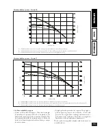
- check that the maximum, intermediate and minimum gas
flowrate and relative pressure values comply with those
given in the handbook on page 32;
- check activation of the safety device in the event of no gas,
and the relevant intervention time;
- check activation of the main switch ahead of the boiler
and on the unit;
- check that the intake and/or exhaust terminals are not
blocked;
- check activation of the regulation devices;
- seal the gas flow regulation devices (if the settings are
modified);
- check the production of hot domestic water;
- check the tightness of water circuits;
- check ventilation and/or airing of the installation room
where provided.
If any safety checks give negative results, do not start the
boiler.
Remote Friend Control or Room ermostat:
e boiler is arranged for application of a Room thermostat or the
Remote Friend Control (C.A.R.). Connect the Room ermostat to
terminals 40 and 41 and remove jumper X20. e Remote Friend
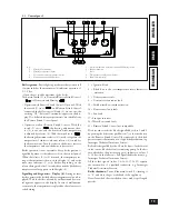
3.1 Wiring diagram - Victrix 20.
Control must be connected to terminals 42 and 43 of the electronic
card, respecting the polarity and removing jumper X20.
M2 - Fan
PU1 - “Block” reset
S1
- Main rotary switch
S2
- Pump flow microswitch
S3
- Domestic circuit priority microswitch
T1
- Voltage transformer
TA
- Room thermostat On/Off (optional)
U1
- Rectifier inside the gas valve connector (present on Honeywell and Dungs gas valves)
X20 - Room thermostat or Remote Friend Control inhibitor jumper
Y1
- Gas valve
white black
black
black
black
black
white
white
white
white
white
red
red
red
red
red
red
pink pink
purple brown
brown
orange
brown
brown
purple
purple
pink
orange
grey
grey
grey
grey
orange
gey-green
re
d-
bla
ck
red-black brown
red-black
wh
ite
-b
lue
wh
ite
-b
lue
re
d-
bla
ck
blue
blue
blue
N.B.
The rectifier U1 is present on boilers equipped
with Honeywell and Dungs gas valve
N.B.
The connectors edged in black are
inserted on the ignition unit
Power supply
Zone station
(optional)
IGNITION/
DETECTION
UNIT
ADJUSTMENT
CARD
DISPLAY CARD
Auxiliary
output
Key:
B1
- Heating NTC sensor
B2
- Domestic circuit NTC sensor
B3
- External sensor (optional)
CAR - Remote Friend Control (optional)
DL1 - Heating mode LED
DL2 - Domestic mode LED
DL3 - Flame presence LED
E1-E2 - Igniters
E3
- Igniter sensor
E4
- Temperature safety thermostat
M1 - Circulating pump
20
INST
ALLER
USER
TECHNICIAN
21
INST
ALLER
USER
TECHNICIAN