Immergas VICTRIX ZEUS 20 Скачать руководство пользователя страница 15

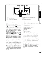
1.9  Filling of system.

After the boiler is connected, fill the system by means of 

the filler cock (see fig. page 16, 17 and 20). Filling must be 

done slowly to ensure the release of air bubbles in the water 

through the boiler and heating system relief valves.

e boiler has a built-in automatic air valve on the expansion 

tank, located on the side of the sealed combustion chamber. 

Check that the cap is loosened. Open the relief valves on the 

radiators. Close the relief valves when only water comes out. 

Close the filler cock when the boiler pressure gauge indicates 

approx. 1.2 bar.

N.B.:

 During this operation, start the circulating pump at 

intervals by means of the main switch on the control panel. 

Vent the circulating pump by unscrewing the front cap and keep-

ing the motor running.

 Tighten the cap on completion.

1.10  Condensate trap filling.

With  the  first  boiler  lighting  fumes  may  come  out  the 

condensate drain; after a few minutes’ operation check that 

fumes no longer come out. is means that the trap is filled 

with  condensate  to  the  correct  level  thus  preventing  the 

passage of fumes.

1.11  Gas system start-up.

To start up the system proceed as follows:
- open windows and doors;
- avoid the presence of sparks or naked flames;
- vent all air from pipelines;
-  check gas supply tightness with the boiler gas ON/OFF 

cock closed; no gas flow must be indicated on the meter 

for 10 minutes.

1.12  Boiler start-up (lighting).

For issue of the Declaration of Conformity provided for by 

Italian Law, the following must be done for boiler start-up:

- check gas supply circuit tightness with the 0n/Off valve 

closed and subsequently open with gas valve closed; no gas 

flow must be read on the meter for 10 minutes;

- ensure that the type of gas used corresponds to that for 

which the boiler is arranged;

- switch on the boiler and ensure correct ignition;
- make sure that the gas flowrate and relevant pressure values 

comply with those given in the manual (see page 32);

- ensure that the safety device activates in the event of no gas 

and check activation time;

- check activation of the main switch generally located ahead 

of the boiler and on the unit;

- check that the concentric intake/exhaust terminal (if fitted) 

is not blocked.

e boiler must not be started up in the event of negative 

result of any of the above checks.

Preliminary boiler testing must be performed by a qualified tech-

nician. e boiler warranty is valid as of the date of testing.

e test and warranty certificate is issued to the user.

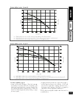
1.13  Circulating pump.

“Victrix” range boilers are supplied with a built-in circulating 

pump with 3 or 4-position electric speed control (depending 

on  the  circulating  pump).  e  boiler  does  not  operate 

correctly  with  the  circulating  pump  on  first  and  second 

speed. To ensure optimal boiler operation, with new systems 

(single pipe and modul) it is advisable to use the circulating 

pump at maximum speed. e circulating pump is already 

fitted with a capacitor.

Pump release.

 If, after a prolonged period of inactivity, the 

circulating pump is blocked, unscrew the front cap and turn 

the motor shaft using a screwdriver. Take great care during 

this operation, to avoid damaging the motor.

14

INST

ALLER

USER

TECHNICIAN

15

INST

ALLER

USER

TECHNICIAN

Содержание VICTRIX ZEUS 20

Страница 1: ...GB Instruction booklet and warning Installer User Technician VICTRIX 20 27...

Страница 2: ...with the appliance It must be kept in a safe place and read carefully as it contains important information to ensure safe installation use and maintenance Installation and maintenance must be performe...

Страница 3: ...ns 18 2 3 Control panel 19 2 4 Restoring heating system pressure 20 2 5 Draining the system 20 2 6 Anti freeze protection 20 2 7 Casing cleaning 20 2 8 Decommissioning 20 3 Boiler start up preliminary...

Страница 4: ...quired procedures Before installing the appliance ensure that it is delivered in perfect condition if in doubt contact the supplier immediately Packing materials staples nails plastic bags polystyrene...

Страница 5: ...manufacturer declines any responsibility in case of flood ing if the drain valve cuts in Important to preserve the life and efficiency of the domestic circuit exchanger it is advisable to install the...

Страница 6: ...on In addition to the functions described in the previous point the Remote Friend Control enables the user to have under control and at hand all the important information regarding appliance and heati...

Страница 7: ...set on the Remote Friend Control only if the boiler main switch is turned to Domestic Remote Friend Control Important If the Remote Friend Control is used arrange two separate lines in compliance with...

Страница 8: ...tor of the single component does not depend on the type of boiler on which it is installed and is a dimen sional value It is based on the temperature of fluids passing through the ducts and therefore...

Страница 9: ...ncentric horizontal intake exhaust 60 100 Intake and exhaust 9 1 4 m Intake and exhaust 5 2 0 8 m Equivalent length in metres of pipe 80 Terminal complete with concentric vertical intake exhaust 60 10...

Страница 10: ...t length in metres of pipe 60 Equivalent length in metres of pipe 80 Complete vertical exhaust terminal 60 for ducting Intake 2 2 Exhaust 1 9 Intake 1 9 Exhaust 2 6 Intake 1 2 Exhaust 1 6 Exhaust 3 3...

Страница 11: ...boiler inserting the seal 1 not requiring lubrica tion positioning it with the round protrusions downwards in contact with the boiler flange and tighten using the screws supplied with the kit Fit the...

Страница 12: ...levant internal and external rings are fitted Fit the male end smooth of the exhaust pipe 9 up to the stop on the female end of the bend 5 making sure that the internal ring is fitted this will ensure...

Страница 13: ...system Green Range 60 mm rigid and 80 flexible ducting systems can only be used for domestic use and with Immergas condensing boilers In any case ducting operations must respect the provisions contai...

Страница 14: ...s be suitably designed to prevent the possible freezing of condensate inside the fume system and condensate dis charge system trap passivator tank comply with the current relevant national and local r...

Страница 15: ...ollowing must be done for boiler start up check gas supply circuit tightness with the 0n Off valve closed and subsequently open with gas valve closed no gas flow must be read on the meter for 10 minut...

Страница 16: ...pen adjustment screw fully unscrewed Head kPa A Flowrate l h B C Head m H 2 O Polyphosphate dispenser kit by request e polyphos phate dispenser prevents the formation of scale and preserves the origin...

Страница 17: ...with seat for Venturi 13 Electronic control unit 14 Overtemperature safety thermostat 15 Circulating pump 16 Plate type heat exchanger 17 Pump safety pressure switch 18 3 bar safety valve 19 3 way val...

Страница 18: ...Electronic control unit 14 Overtemperature safety thermostat 15 Circulating pump 16 Plate type heat exchanger 17 Pump safety pressure switch 18 3 bar safety valve 19 3 way valve monobloc 20 Adjustabl...

Страница 19: ...ctrical water and gas supplies In case of work or maintenance to structures located in the vicinity of ducting or fume extraction devices and relevant accessories switch off the appliance and after co...

Страница 20: ...iler on Stand by an illuminated horizon tal segment appears on the display In case of malfunction or anomaly the temperature is replaced by the relative error code flashing 1 Ignition block 2 Block du...

Страница 21: ...an antifreeze function that starts the pump and the burner when the system water temperature inside the boiler falls below 4 C e anti freeze function is guaranteed if the boiler is fully operative and...

Страница 22: ...Control or Room ermostat e boiler is arranged for application of a Room thermostat or the Remote Friend Control C A R Connect the Room ermostat to terminals 40 and 41 and remove jumper X20 e Remote Fr...

Страница 23: ...el PTC S1 Main rotary switch S2 Pump flow switch microswitch S3 Domestic circuit priority microswitch T1 Voltage transformer TA Room thermostat On Off optional U1 Rectifier inside gas valve connector...

Страница 24: ...stat 18 Automatic air valve 19 Igniters 20 Expansion tank 21 Air intake pipe 22 Circulating pump 23 Circulating pump pressure switch microswitch 24 One way valve 25 Circulating pump pressure switch 26...

Страница 25: ...hood 19 Air analyzer chamber 20 p gas pressure point 21 Fume analyzer chamber 22 NTC limit and heating control sensor 23 Overtemperature safety thermostat 24 Automatic air valve 25 Igniters 26 Expansi...

Страница 26: ...f CO2 in the fumes with boiler at min output with respect to the following table seal the gas flow regulation devices if the settings are modified after completing conversion apply the sticker include...

Страница 27: ...11 Combustion parameters check For max and min heat output adjustment insert the differential manometer between P1 and P2 see fig on page 23 24 for measuring the gas pressure Bring the boiler to chimn...

Страница 28: ...the system return water is below 4 C the boiler starts up and functions until reaching 42 C 3 17 System delivery temperature too high By operating the jumper 5 page 28 two delivery temperature ranges...

Страница 29: ...mode jumper 5 Heating temperature preselection range 6 RS 232 computer interface VK 4115 V gas valve for Victrix 20 Electronic card 7 Output for fan rpm measurement 8 Max heating power adjustment trim...

Страница 30: ...DUNGS gas valve for Victrix 27 Key 1 Gas valve inlet pressure point 2 Gas valve outlet pressure point 3 Off Set adjustment screw 12 Outlet gas flow regulator 29 INSTALLER USER TECHNICIAN...

Страница 31: ...he screws 1 on the bottom of the casing front pull the bottom of the casing front outwards while at the same time pushing upwards see fig undo the screws 2 on the top of the casing front support sheet...

Страница 32: ...k activation of the device against no gas ionization flame control ensure intervention time is less than ten seconds Visually check for water leaks or oxidation from on con nections and traces of cond...

Страница 33: ...14 1 78 18 1 1 12 2 60 26 5 12 0 10320 1 32 1 69 17 3 0 98 1 30 13 3 0 97 1 90 19 4 10 0 8600 1 11 1 23 12 6 0 82 0 91 9 3 0 81 1 40 14 3 8 0 6880 0 89 0 84 8 6 0 67 0 60 6 1 0 66 0 90 9 2 6 0 5160 0...

Страница 34: ...low limiter rated delivery min pressure Domestic circuit min pressure dynamic Domestic circuit max working pressure D specific delivery according to EN 625 Drawing capacity in continuous operation T 3...

Страница 35: ...x working temperature heating circuit Adjustable heating temperature Pos 1 Adjustable heating temperature Pos 2 Total volume heating expansion tank Heating expansion tank precharge Generator water cap...

Страница 36: ...www immergas com ISO 9001 Certified Company is instruction booklet is made of ecological paper Cod 1 021298 Rev 15 017635 000 04 04...

Отзывы: