background image

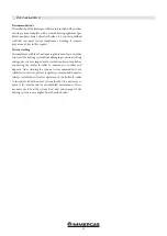
40 cm

40 cm

40 cm

13

Installation

POSITIONING AND LIMITATIONS

For all information and any further clarifications, refer to the 

local national regulations in force. 

The minimum volume of the room where to install the appli-

ance is indicated by the manufacturer and, however, it is greater 

than 15 m

3

.

Check that the room floor is suitable to withstand the weight 

of the boiler.

In the event of simultaneous installation with other central heat-

ing appliances, provide for suitable air inlets for each of them 

(according to the instructions of each product).

It is not permitted to install the product:

• 

in areas that have appliances supplied with 

liquid fuel with continuous or discontinuous 

operation that take combustion air from the 

room in which they are installed, or;

• 

in areas where type B gas appliances are in-

stalled to heat the rooms, with or without pro-

duction of domestic hot water, and in adjacent 

or communicating rooms, or;

• 

in areas in which the measured operating nega-

tive pressure between the external and internal 

technical room exceeds 4 Pa.

It is forbidden to position the product in bedrooms, bath-

rooms, garages and, in general, in places with a fire risk.

BOILER ROOM

Check that the room meets the requirements and characteristics 

of regulations in force. Also, the room must at least provide as 

much airflow as required for regular combustion. Therefore, it 

is required to provide openings on the walls in the room that 

meet the following requirements:

•  Have a minimum free section of 6 cm

2

 for every 1 kW (859.64 

kcal/h). The minimum section of the opening must not be 

less than 100 cm

2

. The section can be calculated by using the 

following:

S = K * Q ≥ 100 cm

2

Where “S” is expressed in cm

2

, “Q” in kW, “K” = 6 cm

2

/kW

•  The opening must be situated in the bottom part of an exter-

nal wall, preferably on the opposite side of the combustion 

gas exhaust.

40 cm

Min.

100 cm

2

Distance from objects

The boiler must be installed in such a way that it can be inspected 

from all sides. Therefore, you must respect a minimum distance 

of 40 cm at the back and sides. It is also recommended to keep 

the pellets and flammable materials at a safe distance.

Содержание LUXOR 16 V2

Страница 1: ...LUXOR V2 16 20 24 28 33 Pellet boiler IE Instructions and warnings Installer Maintenance technician 1 044497ENG 1 044497ENG ...

Страница 2: ......

Страница 3: ... components 17 Connection to the flue 18 Examples of correct installation 18 Hydraulic connection 19 Residual head graphics 22 Filling the boiler 23 Assembling the control panel 23 Configuration of the boiler hydraulic diagram 24 Control unit wiring diagram 24 Boiler ignition 32 Control panel 32 Ignition 32 Information on display 33 Inspections and maintenance 34 Alarm signal 34 Programming menu 3...

Страница 4: ...nments Installation and maintenance must be carried out by qualified staff in compliance with the laws in force in this regard and pursuant to the instructions of the Manufacturer The Manufacturer shall not be held liable in any way should in stallation be carried out by unqualified people and for failure to comply with the general warnings and installation instructions This manual is an integral ...

Страница 5: ...equest original spare parts periodically check and clean the flue exhaust ducts an accumulation of unburnt pellets in the burner after failed ignitionsmustberemovedbeforeproceedingwithnewignition do not use any flammable liquids for ignition do not bring the pellet bag into contact with the boiler when filling the pellet tank make sure the electric system is suitable all local and national laws an...

Страница 6: ...th adequate protection Keep fuel and any flammable materials at a safe distance from the boiler Loading the pellet tank The fuel must be loaded from the upper part of the boiler open ing the door while the boiler is off To facilitate the procedure complete the operation in two stages Pour half the contents into the tank and wait for the pellets to deposit at the bottom Complete the operation by po...

Страница 7: ... to old and or disabled people and especially all children that the boiler is made up of material subject to high temperatures and they must thus be kept away during operation Never touch the boiler with wet hands this is an electric appliance Always disconnect the cable before intervening on the unit The door must always be closed during operation The boiler must be electrically connected to a sy...

Страница 8: ... if the gearmotor stops due to a AL8 MAN AL8 MAN CA DEPRES CA DEPRES or AL7 AL7 SICUREZ TERMICA SICUREZ TERMICA warning the boiler contin ues to operate until the flame goes out as a result of no fuel and until it reaches the mini mum cooling level Automatic vent valve this valve discharges air inside the boiler Safety valve this valve intervenes to prevent hydraulic system overpressure If boiler ...

Страница 9: ...REF Description A1 System flow A2 System return C Pressure discharge valve D Combustion air intake E Flue gas exhaust F Position of main power supply switch G Control panel H Water temperature probe I Thermostat LUXOR 16 V2 boiler dimensions ...

Страница 10: ... 20 24 V2 boiler dimensions Key REF Description A1 System flow A2 System return C Pressure discharge valve D Combustion air intake E Flue gas exhaust F Position of main power supply switch G Control panel H Water temperature probe I Thermostat ...

Страница 11: ... 28 33 V2 boiler dimensions Key REF Description A1 System flow A2 System return C Pressure discharge valve D Combustion air intake E Flue gas exhaust F Position of main power supply switch G Control panel H Water temperature probe I Thermostat ...

Страница 12: ... 15 8 15 8 15 VOLUME THAT CAN BE HEATED data referred to well insulated areas m 3 290 380 430 540 620 MAXIMUM OPERATING PRESSURE bar 2 5 2 5 2 5 2 5 2 5 WATER CONTENT litres 31 50 50 5 60 61 ELECTRIC POWER SUPPLY V hz 220 50 220 50 220 50 220 50 220 50 SPEED IGNITION ABSORBED POWER W 34 330 35 250 35 250 36 250 36 250 FLUE EXHAUST PIPE MM mm 80 80 80 100 100 EXPANSION VESSEL CAPACITY litres 8 8 8 ...

Страница 13: ...red operating nega tive pressure between the external and internal technical room exceeds 4 Pa It is forbidden to position the product in bedrooms bath rooms garages and in general in places with a fire risk BOILER ROOM Check that the room meets the requirements and characteristics of regulations in force Also the room must at least provide as much airflow as required for regular combustion Theref...

Страница 14: ...with a double insulated wall to prevent the onset of condensate The combustion chamber operates in negative pressure DRAUGHT REGULATOR KIT Optional The draught regulator constantly compensates for possible draught variations inside the flue due to outdoor atmospheric conditions If the draught inside the flue increases excessively the oscillating valve adjustable opens and air penetrates into the f...

Страница 15: ... the flue s efficiency The flue or chimney is very important for correct operation of a central heating appliance for solid fuels Therefore it is important that the flue is up to standard and is always kept in perfect efficiency A flue that services a pellet boiler must have minimum category T400 and must withstand soot fire Flue gas exhaust must be conveyed on a single flue with insulated steel p...

Страница 16: ...tegrity of the building The chimney s opening must be in the same room in which the appliance is installed or at most in the adjacent room and to install a soot and condensate collection chamber under the opening which can be accessed from the metal sealed door DIMENSIONING The negative pressure draught of a flue also depends on its height Use suitable tools to check that draught is between 8 Pa a...

Страница 17: ...em s safety CHIMNEY POT The chimney pot is a vital element for the heating appliance to operate well it is recommended to have a windbreaker A type of chimney pot The area provided for flue gas exhaust openings must be minimum double the section of the flue dusted pipe and adjusted in such a way that flue exhaust is ensured even if windy It must prevent rain snow and any animals from entering The ...

Страница 18: ...ar it is recommended to check the flue s data plate for the safety distances to respect in the presence of combustion materials and the type of insulating material to use These provisions must be strictly complied with in order to prevent serious harm to one s health and safeguard the integrity of the building EXAMPLES OF CORRECT INSTALLATION 1 Installation of a Ø150mm flue with boring in order to...

Страница 19: ...id fuel boiler return The valve is not supplied with the boiler The thermostatic diverter valve prevents the re turn of cold water to the heat exchanger and the result ing formation of condensate prolonged contact with condensate will irreparably damage the heat exchanger The lack of an anti condensate device invalidates the warranty Valves with different settings are commercially avail able the m...

Страница 20: ...protect the heating system from damaging corrosion scaling or deposits it is very important to wash the entire system before connecting the boiler in order to remove any residues and deposits After washing the system it is recommended to use inhibitors in order to protect it against corrosion and deposits Always install shut off valves upstream of the boiler in order to insulate it from the water ...

Страница 21: ...mbly diagram LUXOR 16 V2 Not supplied Boiler thermostatic valve assembly diagram LUXOR 20 33 V2 Not supplied Position of safety valve drain LUXOR 16 V2 Position of safety valve drain LUXOR 20 24 V2 Position of safety valve drain LUXOR 28 33 V2 SAFETY VENT VALVE SAFETY VENT VALVE SAFETY VENT VALVE ...

Страница 22: ...0 20 40 60 80 100 120 140 160 180 200 220 240 260 280 300 320 340 360 380 400 420 440 460 480 0 50 100 150 200 250 300 350 400 450 500 550 600 650 700 750 800 850 900 950 1000 1050 1100 LUXOR 16 20 24 LUXOR 28 33 V2 V2 22 Installation GRAPHICS OF RESIDUAL HEAD A PRESSURE HEAD mbar head A PRESSURE HEAD mbar head A RESIDUAL HEAD mbar B FLOW RATE dm3 h B FLOW RATE dm3 h B FLOW RATE dm3 h ...

Страница 23: ... the protective cover and two screws making sure to position the flat cable in the groove on the edge Connect the control panel cable on connector CN5 of the main board refer to the wiring diagram al connettore CN5 Esempio di montaggio su fianco destro FILLING THE BOILER Attention Do not mix the central heating water with antifreeze or anti corrosion substances at incorrect concentrations This may...

Страница 24: ...hermostat open closed the thermostat must not supply voltage to the back CONTROL UNIT WIRING DIAGRAM DHW contact FLUE GAS CONSOLES AND ADDITIONAL ACCESSORIES CONVEYED WAVES NTC S2 upper puffer probe NTC S1 lower puffer probe Boiler NTC probe NTC room probe ext thermostat TCJ flue gas probe If the thermostat turns on the board and causes faults the warranty becomes void two temperature probes and a...

Страница 25: ...rinciples of the various hydraulic diagrams Important observations DHW will always have priority There are three types of stand by Type 01 NOT USED Type 02 the water temperature in the boiler has reached the set SET H2O Type 03 NOT USED How to select the Stand by type Operation carried out by a specialised technician Press the SET key press the key to go to menu 09 Press the SET key Enter the acce...

Страница 26: ...the and key c Press the key to set the working power and adjust it with the and Re starting from the stand by status occurs automatically when more heat is required to return to meet the stand by condition when this is set to ON or when there is a demand for hot water in the puffer I keys Upper thermostat ON OFF on tank Technical water 3 II Lower ON OFF thermostat on tank Technical water 2 Boiler ...

Страница 27: ...O 80 MODULATES PUFFER IN CONTACT LOW THERMOSTAT DOES NOT CALL AND HIGH THERMOSTAT CALLS OFF 01 02 03 WINTER SUMMER ON IF H2O PARAM 25 OPERATION AND IF PROBE H2O 80 MODULATES PUFFER IN CONTACT LOW AND HIGH THERMOSTAT DO NOT CALL ON 01 02 03 WINTER SUMMER OFF STAND BY PUFFER IN CONTACT LOW THERMOSTAT CALLS AND HIGH THERMOSTAT DOES NOT CALL ON 01 02 03 WINTER SUMMER ON IF H2O PARAM 25 OPERATION AND I...

Страница 28: ...hoose the desired degrees c Press the key to set the working power and adjust it with the and keys Re starting from stand by status occurs automatically when the temperature detected by the lower probe of the puffer is lower than the set temperature b Terminal block numerical correspondence for the various electrical connections External thermostat DHW storage tank probe or low puffer probe common...

Страница 29: ...ROBE 80 FORZA STAND BY 2 PROBE PUFFER 4 S1 AND S2 SET PUFFER OFF 01 02 03 WINTER SUMMER ON ON IF H2O S1 AND S2 AND IF H2O PR PUMP ON PROBE H2O 80 MODULATES 2 PROBE PUFFER 4 S1 AND S2 SET PUFFER ON 01 02 03 WINTER SUMMER OFF OFF STAND BY 2 PROBE PUFFER 4 S1 AND S2 SET PUFFER ON 01 02 03 WINTER SUMMER ON ON IF H2O S1 AND S2 AND IF H2O PR PUMP ON PROBE H2O 80 MODULATES It is recommended to set Stand ...

Страница 30: ...ctrical connections External thermostat DHW storage tank probe or low puffer probe common N Upp puffer probe Phase Heat side Phase DHW side Neutral WATER NETWORK THERMOSTATIC MIXING VALVE DHW SYSTEM WITH RECIRCULATION CENTRAL HEATING SYSTEM PUMP MANUAL MIXING VALVE WATER HEAT EXCHANGER Flow Return Water network Puffer probe ACS probe a Press the key to set the temperature in the DHW tank Use the a...

Страница 31: ...OBE H2O 80 PUFFER PROBE ACS STOR AGE TANK ACS PROBE SET ACS AND PUFFER PROBE SET PUFFER OFF 01 02 03 WINTER ON IF H20 5 PUFFER PROBE MODULATES PUFFER PROBE ACS STOR AGE TANK ACS PROBE SET ACS AND PUFFER PROBE SET PUFFER ON 01 02 03 WINTER ON IF H2O SON ACS AND IF H2O PR PUMP ON STAND BY PUFFER PROBE ACS STOR AGE TANK ACS PROBE SET ACS OFF ONLY 2 H2O SUMMER ON IF H2O SON ACS AND IF H2O PR PUMP ON S...

Страница 32: ...rts Key is used to ignite and or switch off the boiler and to exit the program Keys and are used to adjust the temperature for displays and programming functions Keys and are used to adjust the heat power Keys and are used to set the temperature and the pro gramming functions The top and bottom display are used to view various messages Control panel warning Before boiler ignition make sure the pel...

Страница 33: ...s off ACCENDE ON The boiler is in the first ignition phase The glow plug and flue gas extractor are active CARICA PELLET PELLET LOADING At this stage of the ignition process the boiler starts loading pellets into the brazier The glow plug flue gas extractor and auger motor are active FUOCO PRESENTE FIRE PRESENT At this stage of the ignition process the boiler starts loading pellets into the brazie...

Страница 34: ...LAR 7 SICUREZ TERMICA The water temperature exceeds 90 C The circulation pump is blocked or the hydraulic system has no water Check for supply in the pump Check that the pump impeller is not blocked by limescale ALAR 8 MANCA DEPRESS Clogged flue Clean the flue or make sure there are no grids obstructed in flue exhaust outlet ALAR B ERRORE TRIAC COC The auger loads too many pellets Contact the auth...

Страница 35: ...gives the internal clock an autonomy of more than 3 to 5 years Menù 03 Set Crono Set Chrono Press the SET key 3 and then the 5 key to access the desired menu press SET 3 to enter Then enter the M 3 1 menu and use keys 1 and 2 to choose whether or not to enable the chrono thermostat on off which al lows programming of the automatic ignition of the boiler Once the chrono thermostat has been enabled ...

Страница 36: ...nesday prog 2 on off 16 Thursday prog 2 on off 17 Friday prog 2 on off 18 Saturday prog 2 on off 19 Sunday prog 2 on off 20 start program 3 time 21 stop program 3 time 22 Monday prog 3 on off 23 Tuesday prog 3 on off 24 Wednesday prog 3 on off 25 Thursday prog 3 on off 26 Friday prog 3 on off 27 Saturday prog 3 on off 28 Sunday prog 3 on off 29 start program 4 time 30 stop program 4 time 31 Monday...

Страница 37: ...eekly program Allows to enable disable and set the weekly chrono thermostat functions it is possible to set two operating ranges delimited by the set times according to the following table where the OFF setting tells the clock to ignore the command The weekly programmer has 4 independent programmes whose final effect is made up of the combination of the 4 individual programmes The weekly programme...

Страница 38: ...di Program 2 on off 03 03 17 Venerdi Program 2 on off 03 03 18 Sabato Program 2 on off 03 03 19 Domenica Progr 2 on off PROGRAM 3 menu level selection meaning possible values 03 03 20 Start Program 3 activation time ora OFF 03 03 21 Stop Program 3 deactivation time ora OFF 03 03 22 Lunedi Program 3 reference day on off 03 03 23 Martedi Program 3 on off 03 03 24 Mercoledi Progr 3 on off 03 03 25 Gi...

Страница 39: ...ler may emit a small amount of smoke inside the house this is not a safety hazard When the electricity returns the boiler will display AL1 BLACK OUT When the cooling cycle is complete the boiler will restart automatically and go back to the operating status before the blackout Do not attempt to ignite the boiler before the necessary time since it could block it If it is blocked switch off the swit...

Страница 40: ...ely with tips that are mainly vertical or pressed against the back of the furnace The flame must give the impression of being pulled upwards MECHANICAL OR ELECTRONIC FAULTS Anomaly Possible Causes Solutions Pellets are not input into the combustion chamber 1 The pellet tank is empty 2 The auger is blocked by sawdust 3 Auger gearmotor fault 4 Defective P C B 5 One of the manual reset thermostats tr...

Страница 41: ...fective temperature probes 5 Faulty glow plugs 1 Repeat the ignition phase 2 Refer to the instructions above 3 Clean the flue pipe 4 Check and replace the probes 5 Check and replace the glow plug if necessary The pellets accumulate in the brazier the glass of the door is dirty and the flame is weak 1 Insufficient combustion air 2 Damp or unsuitable pellets 3 Flue gas suction motor fault 4 Incorrec...

Страница 42: ...s in order to avoid excessive consumption of combustion ensure the envisaged central heating performance and keep the product intact 3 Check the correct operation of the mandatory anti conden sation valve Cold system in winter but the boiler is boiling 1 The circulator does not turn since it is blocked 2 System with air inside 1 Release the circulator by removing the cap and turning the shaft with...

Страница 43: ... due to the presence of air water does not circulate 1 Check the setting of the pressure reducing valve 2 Installing a water demineraliser 3 Check and clean the DHW kit 4 Replace the plate heat exchanger 5 Bleed the system remove air by venting the radiators Never switch off the boiler by disconnecting the power supply Always let the switching off phase complete otherwise it may damage the structu...

Страница 44: ...circuit flue gas seal gasket combustion chamber door ash drawer fan upper heat exchanger door Internal parts Flue Circulation pump Hydraulic components Electro mechanical components by the user by TAC authorised Technical Assistance Centre BY THE END USER Daily check The boiler requires simple thorough cleaning in order to always ensure efficient performance and normal operation Use the special to...

Страница 45: ...detergents 5 A glass or mirror detergent spray is also good The detergent must not come into contact with skin and eyes If this happens wash under running water and go to the closest health clinic CLEANING PAINTED PARTS Do not clean painted parts with damp cloths when the product is running or hot This is to avoid a thermal shock of the paint and its consequent detachment Silicon paints have techn...

Страница 46: ...ed to remove the pellets completely from the tank using an ash vacuum with a long pipe since if you leave the pellets insides the boiler they may absorb humidity coagulate and make boiler ignition difficult when restarting it in the new season If the control panel display does not start when pressing the main switch at the back of the boiler this could mean the service fuse may need to be changed ...

Страница 47: ...d to vacuum the ashes remove all horizontal connections with a screwdriver and vacuum the ashes once again MAINTENANCE AND CLEANING FOR ALL MODELS BY A SPECIALISED TECHNICIAN These operations must be carried out by a qualified technician or by the user who is responsible for any damage during maintenance This maintenance is to be carried out when the boiler is cold and is not connected to the powe...

Страница 48: ...to the T fittings and any horizontal sections For safety reasons the frequency with which to clean the flue exhaust system is determined according to the frequency of use of the boiler In the event of failed or inadequate cleaning the boiler may have operating problems such as bad combustion blackening of the glass brazier clogging with an accumulation of ashes and pellets deposits of ashes and ex...

Страница 49: ...2019 2015 1187 18 kW LUXOR 20 V2 A A A A A B C D E F G A A A A B C D 2019 2015 1187 21 kW A LUXOR 24 V2 A A A A B C D E F G A A A A B C D 2019 2015 1187 24 kW LUXOR 28 V2 A Inspections and maintenance LUXOR 16 V2 LUXOR 24 V2 LUXOR 28 V2 LUXOR 20 V2 PRODUCT FICHE IN COMPLIANCE WITH EU REGULATION 1187 2015 UE ...

Страница 50: ...50 A A A A B C D E F G A A A A B C D 2019 2015 1187 LUXOR 33 V2 A 29 kW Inspections and maintenance LUXOR 33 V2 ...

Страница 51: ...51 ...

Страница 52: ...This instruction booklet is made of ecological paper immergas com Immergas S p A 42041 Brescello RE Italy Tel 0522 689011 Fax 0522 680617 Cod 1 044497ENG rev ST 004807 000 02 21 ...

Отзывы: