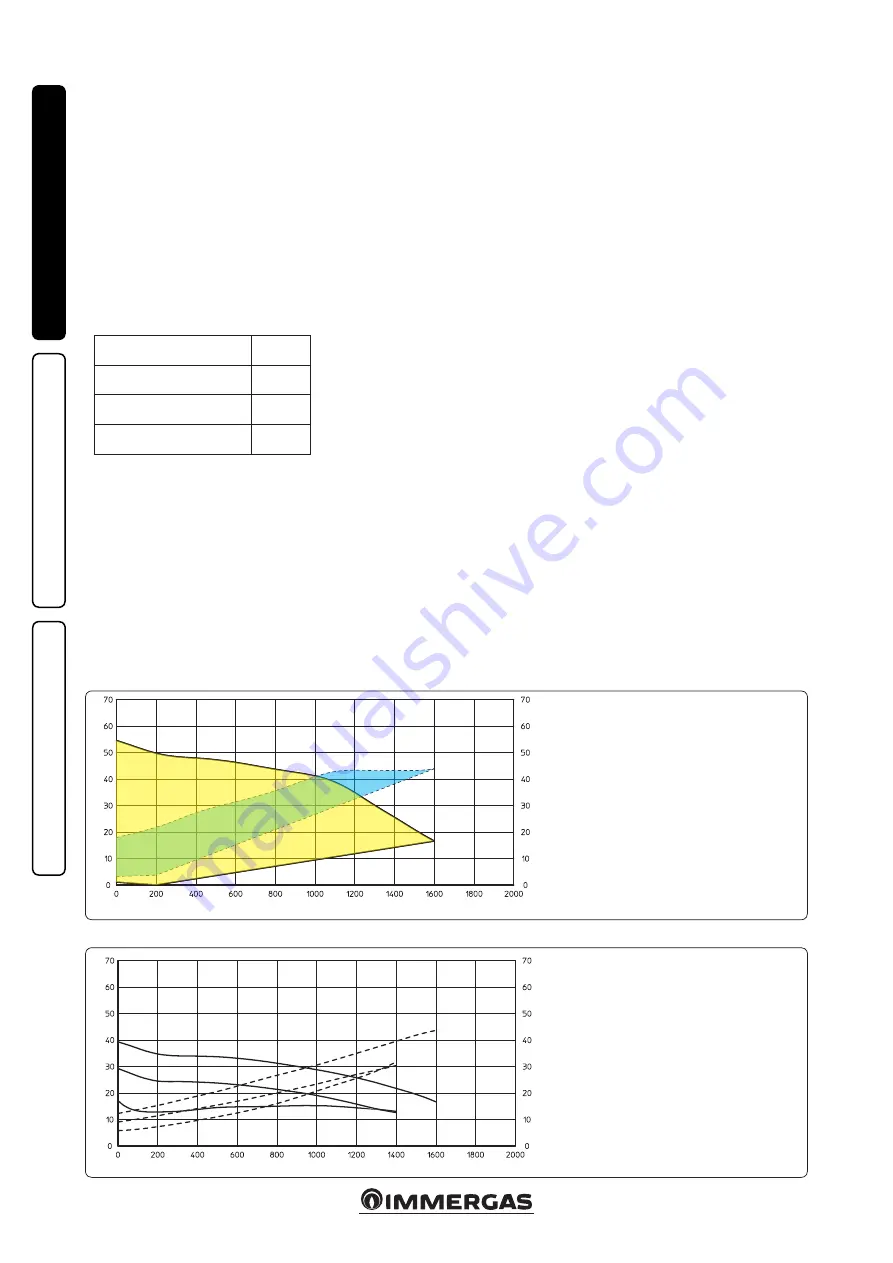
1-24A
1-24B
A
B
C
D
E
F
G
H
18
INS
TALLER
US
ER
MAINTEN
AN
CE TECHNI
CI
AN
pipe installations. Any noise of the water flow
in the pipes, valves and radiators is eliminated
by reducing the head. Optimal conditions for
thermal comfort and acoustic well-being.
Programs C (3 lower 4 upper ) (ΔP-C) -
Constant curve (orange LED).
The circulator
pump maintains the pressure level (head)
constant as the system heat demand decreases
(flow rate reduction). With these settings, the
circulator pump is suitable for all floor systems
where all the circuits must be balanced for the
same drop in head.
MIN-MAX Program (Blue LED).
The pump
is distinguished by adjustable operating curves
by positioning the selector in any point between
the Min and Max positions, thereby satisfying
any installation requirement (from a simple
single-pipe to more modern and sophisticated
systems) and always guarantee optimum per-
formance. The precise working point can be
selected in the entire field of use by gradually
adjusting the speed.
Real time diagnostics:
a lit LED (in various
colours) provides information regarding the
pump operating status, see fig. 1-25
Possible pump release.
The pump block is
indicated by a fixed red LED switching on. Turn
the selector up to the MAX position, discon-
nect and reconnect the power to restart the
automatic release process. The pump will then
activate the procedure that will last a maximum
of 15 minutes and the LED will flash upon each
restart. It then turns blue for a few seconds and
goes back to red if the attempt to restart is not
successful. Once the process is complete, set
the selector back to the desired curve and if
the problem has not bee resolved, perform the
manual release procedure as described below.
- Disconnect the power to the boiler (the LED
switches off).
- Close the system flow and return and let the
pump cool down.
- Empty the system circuit via the relative cock.
- Remove the motor and clean the impeller.
- Once unblocked, remount the motor.
- Fill the primary circuit; restore boiler power
and set the desired curve.
Attention:
there is a burns hazard due to high
fluid temperature and pressure.
Burns hazard
from coming in contact.
1.23 CIRCULATION PUMP.
Boilers in the “Hercules Condensing ErP” series
are supplied with 2 types of circulating pumps.
Set operation modes according to one's installa-
tion requirements.
•
Boiler circulator pump.
The circulating pump
is not equipped with speed selector. To change
operation mode, parameter “P57” in the “M5”
boiler menu must be changed.
•
Zone 1 circulator pump.
The pump is ideal for
the requirements of each central heating system
in a domestic and residential environment.
In fact, the pump is equipped with electronic
control that allows to set advanced functions.
Adjustments.
Turn the selector and set it on
the desired curve to adjust the circulator pump.
Program
LED
P 1 lower (ΔP-V)
P 2 upper (ΔP-V)
green
C 3 lower (ΔP-C) - H=3 m
C 4 upper (ΔP-C) - H=4 m
orange
Min - Max
blue
Program P (1 lower 2 upper ) (ΔP-V) - Pro-
portional curve
(green LED).
This allows
the pressure level (head) to be proportionally
reduced as the system heat demand decreases
(flow rate reduction). Thanks to this func-
tion, the electric power consumption of the
circulator pump is reduced further: the energy
(power) used by the pump decreases according
to the pressure level and flow rate. With this
setting, the pump guarantees optimal perfor-
mance in most heating systems, thereby being
particularly suitable in single-pipe and two-
Key:
C = Head available to the system with circula-
tor pump selector in position C4 (standard
setting)
D = Head available to the system with circula-
tor pump selector in position C3
E = Head available to the system with circula-
tor pump selector in position P2
F = Circulator pump power with selector in
position C4 (standard setting)
G = Circulator pump power with selector in
position C3
H = Circulator pump power with selector in
position P2
Head available to the direct zone system fixed speed.
Head available to the direct zone system proportional or constant speed.
Key:
A = Available head
B = Power absorbed by the circulator
pump (dotted area)
Ci
rcu
la
to
r p
um
p a
bs
or
be
d p
ow
er (
W
)
Ci
rcu
la
to
r p
um
p a
bs
or
be
d p
ow
er (
W
)
Flow rate (l/h)
Flow rate (l/h)
H
ea
d (kP
a)
H
ea
d (kP
a)
MAX
MIN


