background image

Technical documentation

Technical documentation

STEM@  ed 06/01

25

EOLO MAIOR @

OUTPUTS

Modulation coil

(Y2)

This is a D.C. current that controls the modulation coil and permits changing the pressure of
the gas to the burner depending on requested output.

Control zone unit (CZ)

(external optional)

This is a signal that enables the zone unit to know the operating condition of the appliance

(d.h.w./central heating

) and to recognise the CAR,  if fitted, as room thermostat of zone 1

(see control zone unit operation).

Remote control (CAR)

(external optional)

(see CAR operation)

This is a signal that permits displaying on the monitor of the remote control the temperature
of the boiler, operation in d.h.w. or central-heating modes and the codes of the tripped
alarms.

Pump relay  (K1)

This is a unipolar relay for controlling the circulator (M1). It is powered when operation is
requested.

Request relay  (K2)

This is a unipolar relay which is excited when the burner needs igniting.
When its contact closes, the ignition unit is powered.

Reset

In the event of the Remote Friendly Control being installed 

(optional

), this


 signal permits

releasing the ignition unit after the overheat. safety device (E4) and the stack safety device
(E5) have tripped or after ignition failure
This operation is performed on the remote control panel 

(see CAR operation).

ADJUSTMENTS

Central-heating potentiom.

(C.H.)

This permits setting the temperature of the central-heating water between 38 ºC and 85 ºC.

D.h.w  potentiom. (D.H.W.)

(combined models only)

Permits setting the temperature of the d.h.w. between 30 ºC and  60 ºC.

Natural gas/LPG switch

(S1)

Depending on its position 

(natural gas/LPG)

 it adapts the modulation parameters to the type

of gas for which the boiler is set.

D.h.w. modulation switch

(S3)

(B&P board only)

By eliminating this bridge, in d.h.w. phase the burner is kept
operating at minimum output even after reaching the temperature set
with the d.h.w. potentiometer (D.H.W.).
When the temperature read by the d.h.w. sensor (B2) exceeds 65°C,
the burner is switched off and is relit when the temperature drops
below 64 ºC.

absent = modulation

and switchoff at 65 ºC

present = modulation

and switchoff at set

temp.

Central-heating timing (S2)

At every switchoff due to the temperature having been reached in
central-heating phase, a delay of 180 s is entered (

standard

) or of 30

seconds until switching back on for the same request.

absent = 30 s

entered = 180 s

C.H. max power trimmer.

(C.H. MAX POWER)

Permits adjusting max output in central-heating phase and adpating this to system
requirements 

(from minimum to maximum set on gas valve).

C.H. min power trimmer.

(C.H. MIN POWER)

Permits adjusting modulated min output in central-heating phase 

(from minimum up to 2/3 of

maximum set on the gas valve).

Adjustment is possible during the first 60 seconds after ignition in central-heating phase.

Soft ignition trimmer

(IGN. POWER)

Permits adjusting power to the modulation coil and therefore gas pressure to the burner
during ignition phase 

(from min up to 2/3 max set on valve).

Adjustment must be made with the d.h.w. probe (B2) electrically diconnected and can be
made within the first 30 sec of operation in central-heating phase.

Содержание EOLO 21 Maior

Страница 1: ...optional The hydraulic circuit features a copper water gas exchanger an automatic system by pass and a new brass monobloc to which is fitted the hydraulic 3 way valve which ensures according to need circulation of boiler water in the heating system or in a stainless steel plated exchanger for the instantaneous production of d h w Combustion air flow into the sealed chamber and flue extraction are ...

Страница 2: ...at safety thermostat 13 Combustion chamber 14 Circulator 15 System water pressure switch 16 Plated exchanger 17 3 bar safety valve 18 Automatic bypass disengage screw 19 3 way hydraulic valve 20 Positive signal pressure point 21 Negative signal pressure point 22 Draught diverter 23 Primary heat exchanger 24 Ignition and detection electrodes 25 Burner CONTROL PANEL 1 Heating temperature switch 2 D ...

Страница 3: ...1 000 kcal h 24 4 kW and 24 000 kcal h 27 9 kW Adjustment and control of the boiler are entrusted to a microprocessor controlled electronic board thanks to which the appliance can be connected to the Remote Friend Control optional The appliances feature a copper water gas exchanger and a standard antifreeze safety device that protects down to temperatures as low as 5 C MAIN DIMENSIONS AND CONNECTI...

Страница 4: ...it and adjustment probe 11 Overheating safety thermostat 12 Combustion chamber 13 Circulator 14 System water pressure switch 15 3 bar safety valve 16 Positive signal pressure point 17 Negative signal pressure point 18 Draught diverter 19 Primary heat exchanger 20 Ignition and detection electrodes 21 Burner CONTROL PANEL 1 Heating temperature switch 2 Red ignition stop indicator 3 Burner operating ...

Страница 5: ...e is a central heating or domestic hot water request OPERATION The heat contained in the combustion products is absorbed by the copper blades of the water gas exchanger 8 which in turn transfers this heat to the water circulating inside thanks to the boiler pump 17 In the case of the models for central heating only S the water flows directly into the system while in the case of boilers with d h w ...

Страница 6: ...engaged EOLO 21 Maior EOLO 21 Maior S EOLO 24 Maior EOLO 24 Maior S EOLO 27 Maior PRIMARY EXCHANGER This is a water gas blade exchanger with pipes and fins in copper at the outlet delivery of which are positioned the NTC heating sensor 6 and the overheating safety thermostat 2 The size and layout of the pipes differ according to boiler output In the 21 and 24 versions the four pipes making it up a...

Страница 7: ...downstream of the stopcock an one way valve is fitted 6 disconnector that prevents accidental flow of water from the primary circuit to the water network d h w circuit System water pressure switch 3 This reads the pressure inside the primary circuit It is housed in the enbloc and is coupled to a microswitch that prevents boiler operation when the read pressure is below 0 3 bar This way overheating...

Страница 8: ... water absorbs the heat in the primary circuit see d h w exchanger In this phase the central heating function is disengaged and priority is given to the production of d h w DOMESTIC HOT WATER EXCHANGER This is a water water exchanger consisting of STAINLESS steel plates placed one on top of the other 15 in version 21 and 19 in version 24 21 in version 27 on the surface of which runs in counterflow...

Страница 9: ...ssembled cartridge used during production and the pre assembled cartridge used as a spare are interchangeable with those fitted on previous MAIOR versions despite rods 8 9 being used with 3 mm diameter and O R rings in EPDM peroxide that give these greater resistance to mechanical and chemical stress At the cold water inlet is a flow limiting device 5 the value of which differs according to applia...

Страница 10: ...ssure difference between the two points is such as to cause the movement of the diaphragm 1 The movement is conveyed to the rods 8 9 and plate 2 which first of all cause shutter 3 to move and then the d h w microswitch 7 to close with consequent powering of the pump and modulation board In this condition the return pipe R is closed while the opening is open towards the exchanger inside which the w...

Страница 11: ...e ignited These are electrically connected in series and energised by rectified mains power through a diode bridge inside the special connector 2 Modulation coil 1 This is a low voltage coil controlled by the modulation board It controls the gas valve stabiliser and permits changing the outlet pressure in a way proportionate to the DC current that runs through it Honeywell VK 4105 M BURNER The bur...

Страница 12: ...rner and anticlockwise to decrease pressure 1 Modulation coil 5 Yellow protection cap 2 Coil pin 6 Gas valve outlet press point 3 Min output adjust screw 7 Valve inlet press point 4 Max output adjust screw 8 Air press point hose connector VALVE VK 4105 M M with integrated flanges with transparent protection cap Maximum pressure adjustment Draw d h w after setting the temperature switch at maximum ...

Страница 13: ...ng to the modulation board of the NATURAL GAS LPG S1 bridge The minimum and maximum pressures are then set on the gas valve in the way described above Adjustment of the minimum and maximum output version 27 only during the heating phase and of burner ignition pressure see table below can be done by means of the respective trimmers mounted on the modulation board see modulation board operation Slow...

Страница 14: ...eration of which enables or does not enable burner ignition AIR FLUE SAMPLING SUMPS 6 7 The top outer part of the chamber features two sumps with screw closing accessible from the front and through which combustion air 6 and flues 7 can be extracted FLUE PRESSURE SWITCH SIGNAL PRESSURE POINT 8 9 The top outer part of the sealed chamber features two pressure points with screw closing for measuring ...

Страница 15: ...e extraction exhaust terminals and is measured by the special pressure points fitted to the top part of the sealed chamber 8 9 Its operation causes a deviation of a switch contact that acts on the unit IGN BOARD and enables or fails to enable burner ignition FAN 4 The extractor operates downstream of the combustion chamber and is physically rested on the top part of the hood 3 from which it extrac...

Страница 16: ...re used extraction is done through the concentric hole outside the exhaust pipe 5 EXTRACTION EXHAUST KIT The kits and relevant accessories make it possible to use four concentric systems and two doubled systems As regards pressure drop relating to each accessory the various possible combinations and the use of the diaphragms to be fitted according to the length of the pipes see the instructions co...

Страница 17: ...sible overall length is 12 2 straight and vertical metres 80 80 coupling type separator kit Both pipes have a diameter of 80 mm Connections to the boiler are made using two special flanges for exhaust 1 from the centre pipe and extraction 2 from one of the two side holes Max possible length extraction exhaust is 33 straight horizontal metres and 41 straight vertical metres To prevent condensation ...

Страница 18: ...ols the ignition unit and enables burner operation when fume extraction occurs correctly If this is closed with the fan off the ignition cycle will not start Two position switch Overheat safety device E4 When the safety threshold is exceeded 115 ºC this interrupts power to the main coils of the gas valve Y1 It is located at the outlet of the primary exchanger Double contact clicson thermostat LOAD...

Страница 19: ... switch S5 0 RESET low voltage circuit not powered d h w operation combined models only and CAR optional d h w and central heating operation release after tripping of ignition failure temperature and stack safety device the RESET position works at the mains voltage by closing a contact that controls the ignition unit 3 position double switch reset button D h w switch S6 combined models only Follow...

Страница 20: ...cle by first checking the correct position of the flue pressure switch S4 and then powering fan M2 After the contact of flue pressure switch S4 has been deviated by fan operation M2 the unit IGN CARD powers the ignition electrodes E1 E2 and with the consensus of the overheat safety thermostat E4 the main coils of gas valve Y1 Burner ignition is detected by the unit by means of the ionisation elect...

Страница 21: ...re switch S7 reads a pressure in the primary circuit above minimum value S7 switch closed and if the temperature read by the NTC heating sensor B2 is below the setting made on the control panel or on the CAR if fitted by means of the heating potentiometer the board closes the contact of the requested relay K2 This way the ignition unit IGNITION CARD starts the ignition cycle by first checking the ...

Страница 22: ... thermostat TA contact is closed the low voltage circuit starts the circulator M1 and powers relay K1 If the system water pressure switch contact S7 is closed and the temperature read by the NTC heating sensor B1 is below that set using the heating potentiometer C H the low voltage circuit excites relay K2 This results the ignition card powering and the start of the ignition cycle After the gas va...

Страница 23: ...y this power is increased so as to immediately achieve if requested the max set value During operation modulation is performed with reference to the difference between the temperature set using the d h w potentiometer D H W and the temperature read by the d h w sensor B2 When the set temperature is reached the burner is kept operating at minimum output and the contact of relay K2 is opened burner ...

Страница 24: ...bridge X20 Main switch S5 This is a double switch which depending on its position either powers or does not power the low voltage circuit 24 Vdc and indicates whether d h w CAR function is enabled SUMMER or d h w and central heating WINTER Switch S5A open circuit OFF closed circuit ON Switch S5B open SUMMER closed WINTER System water pressure switch S7 When the primary circuit pressure is below 0 ...

Страница 25: ...combined models only Permits setting the temperature of the d h w between 30 ºC and 60 ºC Natural gas LPG switch S1 Depending on its position natural gas LPG it adapts the modulation parameters to the type of gas for which the boiler is set D h w modulation switch S3 B P board only By eliminating this bridge in d h w phase the burner is kept operating at minimum output even after reaching the temp...

Страница 26: ... running for 150 seconds NTC sensors fault B1 and B2 A fault in the d h w sensor B2 prevents operation in d h w mode A fault in the central heating sensor B1 prevents operation in both central heating and d h w mode Breakage is indicated by the flashing of LED H1 yellow INDICATORS H1 yellow LED H2 red LED H3 green LED CAR error code monitor if fitted Depending on state these indicate off off off b...

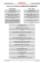
Страница 27: ...or POWERING THE IGNITION UNIT If the contact of the system water pressure switch is closed the modulation board controls the ignition card FLUE PRESSURE SWITCH CONTACT CONTROL The unit checks the correct position of the flue pressure switch normally closed NC contact POWERING FAN The ignition card powers the fan FLUE PRESSURE SWITCH CONTACT CONTROL The ignition cards checks deviation of the flue p...

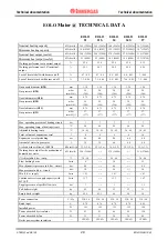
Страница 28: ...8 Gas pressure G31 mbar mm H2O 37 377 37 377 37 377 37 377 37 377 Max operating pressure of heating circuit bar 3 3 3 3 3 Max operating temp of heating circuit ºC 90 90 90 90 90 Adjustable heating temp ºC 38 85 38 85 38 85 38 85 38 85 Total volume of expansion vessel l 8 8 8 8 10 Expansion vessel preloading bar 0 8 0 8 0 8 0 8 0 8 Amount of water in generator l 3 5 3 5 4 0 4 0 4 4 Available head w...

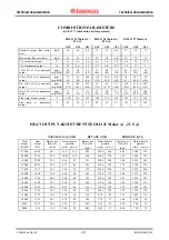
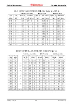
Страница 29: ...6 129 131 130 Flue temp at minimum output ºC 93 93 95 89 93 97 101 107 105 HEAT OUTPUT ADJUSTMENTS EOLO 21 Maior 21 S NATURAL GAS G20 BUTANE G30 PROPANE G31 Heat output Kcal h Heat output kW Burner gas flow rate m3 h Burner nozzle pressure mbar mm H2O Burner gas flow rate kg h Burner nozzle pressure mbar mm H2O Burner gas flow rate kg h Burner nozzle pressure mbar mm H2O 21000 24 42 2 81 11 0 112 ...

Страница 30: ...00 10 5 1 28 1 70 17 0 95 5 20 53 0 94 7 10 72 HEAT OUTPUT ADJUSTMENTS EOLO 27 Maior NATURAL GAS G20 BUTANE G30 PROPANE G31 Heat output Kcal h Heat output kW Burner gas flow rate m3 h Burner nozzle pressure mbar mm H2O Burner gas flow rate kg h Burner nozzle pressure mbar mm H2O Burner gas flow rate kg h Burner nozzle pressure mbar mm H2O 27000 31 4 3 63 12 01 122 2 71 27 02 276 2 67 35 02 357 260...

Отзывы: