Immergas 3.025615 Скачать руководство пользователя страница 31

31

3-3

INS

TALLER

US

ER

MAINTEN

AN

CE TECHNI

CI

AN

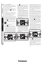
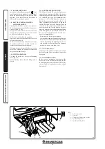
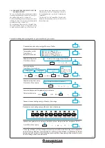
3.3  INSTALLATION EXAMPLE HYDRAULIC DIAGRAM .

Key:

  1 -  Boiler

  2  -  External temperature probe

  3 -  Comando amico remoto remote control 

V2

 (CAR

V2

)

  4  -  Heat pump

  5  -  Heat pump remote panel

  AC  -  Domestic hot water outlet

  AF  -  Domestic cold water inlet

  RHT  -  Return to heat pump

  MHT  -  Flow from heat pump


M  -  System flow


R  -  System return

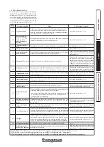
3.4 TROUBLESHOOTING.

N.B.:

 maintenance operations must be carried 

out by an authorised company (e.g. Authorised 

After-Sales Technical Assistance Service).
-  Smell of gas. Caused by leakage from gas circuit 

pipelines. Check sealing efficiency of gas intake 

circuit.

- Repeated ignition blocks. No gas, check the 

presence of pressure in the network and that 

the gas adduction cock is open. Incorrect 

adjustment of the gas cock, check the correct 

calibration of the gas valve.

- Irregular combustion or noisiness. It may be 

caused by: a dirty burner, incorrect combustion 

parameters, intake-exhaust terminal not cor-

rectly installed. Clean the above components 

and ensure correct installation of the terminal, 

check correct setting of the gas valve (Off-Set 

setting) and correct percentage of CO

2

 in flue 

gas.

- Frequent interventions of the overheating 

safety thermostat. It can depend on the lack 

of water in the boiler, little water circulation 

in the system or blocked pump. Check on the 

manometer that the system pressure is within 

established limits. Check that the radiator 

valves are not closed and also the functionality 

of the pump.

- Drain trap clogged. This may be caused by 

dirt or combustion products deposited inside. 

Check, by means of the condensate drain cap, 

that there are no residues of material blocking 

the flow of condensate.

- Heat exchanger clogged. This may be caused 

by the drain trap being blocked. Check, by 

means of the condensate drain cap, that there 

are no residues of material blocking the flow of 

condensate.

- Noise due to air in the system. Check open-

ing of the special air vent valve cap (Part. 28 

Fig. 1-27). Make sure the system pressure and 

expansion vessel pre-charge values are within 

the set limits; The factory-set pressure values of 

the expansion vessel must be 1.0 bar, the value 

of system pressure must be between 1 and 1.2 

bar.

- Noise due to air inside the condensation 

module. Use the manual air vent valve (Part. 

14 Fig. 1-27) to eliminate any air present in the 

condensation module. When the operation has 

been performed, close the manual vent valve.

- System low circulation. Check the boiler, 

system and heat pump circulator pumps is 

working properly.

- Heat pump not working. Check that the heat 

pump is powered and the presence of errors 

on the relative control panel (see heat pump 

instructions manual).

SYSTEM
CENTRAL HEATING
COOLING

WATER-DHW NET-

WORK

Содержание 3.025615

Страница 1: ...MAGIS VICTRIX ERP IE Instruction and recommendation booklet 1 038946ENG...

Страница 2: ......

Страница 3: ...fessionals within the dimensional limits established by the Law Installation and maintenance must be performed in compliance with the regulations in force according to the manufacturer s instructions...

Страница 4: ...2 5 Using the boiler 24 2 6 Troubleshooting 25 2 7 Parameters and information menu 27 2 8 Boiler shutdown 28 2 9 Restore central heating system pressure 28 2 10System drainage 28 2 11Anti freeze prot...

Страница 5: ...damaged if the safety valve intervenes with an obstructed conveying system the safety valve must be conveyed away by a draining funnel or if there are leaks from the hydraulic connections on the contr...

Страница 6: ...be followed scrupulously regarding the percentage neces sary with respect to the minimum temperature at which the system must be kept An aqueous solution must be made with potential pollu tion class o...

Страница 7: ...escopic fitting 3 4 R RHT MHT M N 1 Rubber fitting for condensate drainage SC N 1 Condensate drainage corrugated pipe SC N 1 Extension for filling valve N 1 Filling valve N 1 Condensation collection t...

Страница 8: ...ecial pickling or descaling products to remove any deposits that could compromise correct boiler operation A chemical treatment of the thermal system wa ter is required in compliance with the technica...

Страница 9: ...r is made using wires with a minimum section of 0 50 mm2 and maximum section of 2 5 mm2 and with a maximum length of 50 metres External temperature probe electrical con nection Theboileronlyworksifiti...

Страница 10: ...pipe length for each type of Terminal Kit This information allows calculations to be made to verify the possibility of setting up various flue configurations Positioning the gaskets black for green ra...

Страница 11: ...Intake and Exhaust 16 3 m 2 5 Intake m 18 7 Exhaust m 4 9 m 7 7 Exhaust m 13 6 Concentric vertical intake exhaust terminal 60 100 Intake and Exhaust 9 m 1 4 Intake m 10 3 Exhaust m 2 7 m 4 3 Exhaust m...

Страница 12: ...ent in the kit positioning the relevant gaskets Engage the 90 80 bend with the male end smooth in the female end with lip seal of the 80 flange unit until it stops Introduce the gasket making it run a...

Страница 13: ...orizontal m in cluding the terminal with grid and excluding the concentric bend leaving the boiler This configurationcorrespondstoaresistancefactor of 100 In this case the special extensions must be r...

Страница 14: ...cal length of 14 4 m including the terminal This configuration corresponds to a resistance factor of 100 In this case specific extensions must be requested Vertical kit with aluminium tile 80 125 Kit...

Страница 15: ...th the male side smooth in the female side of the bend 5 up to the end stop ensuring that the internal and external wall sealing plates are fitted Fit the exhaust pipe 9 with the male side smooth to t...

Страница 16: ...ical data The dimensions of the shafts must ensure a minimum gap between the outer wall of the smoke duct and the inner wall of the shaft 30 mm for circular section shafts and 20 mm in the event of a...

Страница 17: ...th is obtained considering the complete 80 exhaust terminal 1m of 80 pipe in ex haust two 90 80 bends on the boiler outlet 1 16 CONFIGURATION TYPE B OPEN CHAMBER AND FAN ASSISTED FOR INDOORS The appli...

Страница 18: ...ns featured on the boiler active upon initial ignition and on the heat pump see relative instructions booklet Vent the boiler circulation pump by loosening the front cap and keeping the motor running...

Страница 19: ...level from a minimum one to a maximum one by turning the selector switch clockwise in the relative power scale Proportional head program P V 3 fig 1 25 This allows the pressure level head to be propo...

Страница 20: ...functioning characteristics of the boiler thanks to its inspectionable filter Kit with two motorised areas on request In the event one wants to divide the thermal sys tem in two areas to interlock the...

Страница 21: ...on module 14 Manual air vent valve 15 Negative signal pressure point 16 Positive signal pressure point 17 Sample points air A flue gas F 18 Flue safety thermostat 19 Heat exchanger safety thermal fuse...

Страница 22: ...d to weathering rain sunlight etc the appliance power cable must not be re placed by the user if the cable is damaged switch off the ap pliance and solely contact an authorised company to replace it i...

Страница 23: ...fter a request for domestic hot water or central heating in order to evacuate residual flue gas F5 Postcirculation in progress Pump in function after a request for domestic hot water or central heatin...

Страница 24: ...ting stage if the water temperature is sufficient to heat the system the boiler can operate just with the activation of water circulation Winter operation mode with room central heating with boiler 2...

Страница 25: ...on circuit or anomaly in the flame control unit Press the Reset button 1 2 23 Return probe anomaly The board detects an anomaly on the system return NTC probe The boiler does not start 1 2 24 Push but...

Страница 26: ...g and cooling are inhibited Check the type of anomaly directly on the remote panel display see relative instruc tions manual In the event the heat pump does not fea ture any anomaly check that the dom...

Страница 27: ...ntenance chapter By turning the central heating temperature se lector switch 3 scroll through the menu items By pressing button D access the various levels of the menu and the choice of parameters is...

Страница 28: ...Victrix ErP series boiler features an anti freeze function that lights the burner automatically when the temperature falls below 4 C standard protection up to minimum tem perature of 3 C All informat...

Страница 29: ...omestic hot water check sealing efficiency of water circuits check ventilation and or aeration of the instal lation room where provided If even only a single safety check offers a negative result do n...

Страница 30: ...re point 22 Flue sample point 23 Fumes hood 24 Heat exchanger safety thermal fuse 25 Delivery probe 26 Safety thermostat 27 Ignition electrodes 28 Burner 29 Condensation module cover 30 Return probe 3...

Страница 31: ...tle water circulation in the system or blocked pump Check on the manometer that the system pressure is within established limits Check that the radiator valves are not closed and also the functionalit...

Страница 32: ...in the table Par 3 20 3 6 CALIBRATION OF NUMBER OF FAN REVS Attention verification and calibration is neces sary in the case of transformation to other types of gas in the extraordinary maintenance ph...

Страница 33: ...ating selector switch to maxi mum turn it in a clockwise direction until 99 is seen on the display To have an exact value of CO2 in the flue gases the technician must insert the sampling probe to the...

Страница 34: ...efines the maximum flow tempera ture corresponding to operation with minimum external temperature see graph Fig 1 5 it can be set between 50 C and 85 C N B to continue one must confirm the parameter p...

Страница 35: ...to automatic functioning therefore with variable flow rate Open adjuster completely open therefore maximum flow rate available 09 L M 12 L M and 15 L M operation with defined flow AUTO RELAY1 RELE1 0...

Страница 36: ...event the boiler circulator pump is replaced with a traditional fixed speed circulator pump one must connect the new circulator pump to the relay board P76 15 C 14 C CE With S34 On If the reading of...

Страница 37: ...HEATING OPERATION IN COMBINATION WITH THE HEAT PUMP Following a request during the room heating mode the electronics decide according to the external temperature whether to activate the heat pump or w...

Страница 38: ...han that set by the do mestic hot water selector switch SET the boiler does not switch on 3 18 YEARLY APPLIANCE CHECK AND MAINTENANCE The following checks and maintenance should be performed at least...

Страница 39: ...screws 11 disassemble the front 1 of the boiler by loos ening the screw 2 by 1 4 turn push the front upwards while pulling it towards you at the same time to release it from the side 3 and upper 4 ho...

Страница 40: ...17200 2 16 3 48 35 5 1 61 3 40 34 7 1 58 4 54 46 3 19 0 16340 2 05 3 17 32 3 1 53 3 10 31 6 1 50 4 15 42 4 18 0 15480 1 94 2 87 29 3 1 45 2 81 28 6 1 42 3 79 38 7 17 0 14620 1 84 2 59 26 5 1 37 2 53...

Страница 41: ...ss at casing with burner On Off 80 60 C 0 49 0 70 Heat loss at flue with burner On Off 80 60 C 0 02 1 90 Central heating circuit max operating pressure bar 3 Maximum heating temperature C 90 Adjustabl...

Страница 42: ...r N Serial Number CHK Check Cod PIN PIN code Type Type of installation ref CEN TR 1749 Qnw min Minimum DHW heat input Qn min CH minimum heat input Qnw max DHW maximum heat input Qn max CH maximum heat...

Страница 43: ...0 071 kW At partial load elmin 0 010 kW Ignition burner energy consumption Pign 0 000 kW In standby mode PSB 0 005 kW Emissions of nitrogen oxides NOX 23 mg kWh For mixed central heating appliances St...

Страница 44: ...ementary heat pump From fiche of heat pump Solar contribution and Supplementary heat pump Select smaller value Boiler and supplementary heat pump installed with low temperature heat emitters at 35 C F...

Страница 45: ...e energy efficiency of the package of products provided far in this fiche may not correspond to its actual energy efficiency once installed in a building as the efficiency is influenced by further fac...

Страница 46: ...contribution From fiche of solar device 1 I 2 1 1 x I 10 x II III I Auxiliary electricity 3 G F E D C B A A A A 27 27 27 28 27 27 27 28 30 30 30 32 33 34 35 36 36 37 38 40 39 50 55 60 65 75 80 85 100...

Страница 47: ...ncy under colder and warmer climate conditions Colder 0 2 x Warmer 0 4 x Declared load profile Solar contribution From fiche of solar device 1 ___ 2 1 1 x ___ 10 x ___ ____ ____ Auxiliary electricity...

Страница 48: ...mmergas S p A 42041 Brescello RE Italy Tel 0522 689011 Fax 0522 680617 Certified company ISO 9001 This instruction booklet is made of ecological paper Cod 1 038946ENG rev ST 002042 001 06 19 Inglese p...

Отзывы: