


3
Applications
The power mixer PMX-150DSP is a combination of
a 7-channel mixer and a 2 x 100 W power amplifier.
It is especially suitable for musicians and stage
applications. It is possible to connect to the input
channels units with line output (musical instrument,
CD player, tape deck, etc.) and microphones (also
phantom-powered) and to add them to a master sig-
nal as well as to a monitor way.
Due to the internal effect processor with 15 differ-
ent effects it is possible to add an effect to the
master signal separately from each input channel.
The effect can also be switched on and off via a
connected foot switch. In addition, the unit offers the
facility to insert an external effect unit via the Send
and Return connections.
4
Connection of the Units
Prior to the connection or changing of connections
switch off the PMX-150DSP and the units to be
connected.
4.1
Microphones
1) If the microphones used do not need a phantom
power, set switch PHANTOM POWER (26) to
position OFF. In this case both balanced as well
as unbalanced microphones can be connected.
2) For the operation of phantom-powered micro-
phones set switch PHANTOM POWER to posi-
tion ON. The 48 V phantom power is present at
all XLR jacks MIC (9).
3) Connect the microphones to the XLR jacks MIC
(9).
Note: The inputs cannot be switched between jacks
MIC (9) and LINE (8). Therefore, connect to each
channel either the XLR jack MIC or the 6.3 mm jack
LINE.
4.2
Musical instruments and units with line
output
Connect signal sources with line mono output (e. g.
musical instruments) to jacks LINE (8). When con-
necting stereo units (CD player, tape deck, etc.)
switch them to mono or use a corresponding adapt-
er (e. g. NTA-169, MCA-300 by MONACOR), other-
wise a channel is phase-reversed (stereo differential
signal). Stereo units may also directly be connected
to the jacks AUX (17) and TAPE (18).
Note: connect either the 6.3 mm jack LINE (8) or the
XLR jack MIC (9) to each input channel.
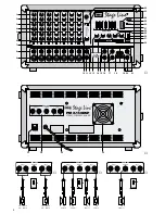
4.3
Speakers
Connect the speaker/s to the OUTPUT (34) accord-
ing to the desired speaker configuration (figs. 3 to 5).
For the left and right channels the two jacks A and B
are each connected in parallel.
1. For connecting one speaker per channel, connect
the speaker for the left channel to one of the two
jacks LEFT, and the one for the right channel to one
of the two jacks RIGHT – see fig. 3. The impedance
of the speakers must be 4
Ω
as a minimum. Set the
switch MODE (30) to position STEREO.
Each 4
Ω
speaker must have a power capabil-
ity of 100 W
RMS
as a minimum. If 8
Ω
speakers
are used, each speaker must have a power capa-
bility of 65 W
RMS
as a minimum.
2. For connecting two speakers per channel,
connect those for the left channel to the two jacks
LEFT and those for the right channel to the two
jacks RIGHT – see fig. 4. The impedance of the
individual speakers must be 8
Ω
as a minimum,
and each speaker must have a power capability
of 50 W
RMS
as a minimum. Set switch MODE (30)
to position STEREO.
3. For connecting one speaker in mono bridge
operation, connect it to jack BRIDGE, and set
switch MODE (30) to position L+R BRIDGE – see
fig. 5. The speaker impedance must be 8
Ω
as a
minimum and the power capability 200 W
RMS
as
a minimum.
4.4
Recording unit
1) For audio recordings connect the input of a record-
ing unit to the phono jacks REC (19). At these
jacks the master signal is present which is, how-
ever, not influenced by the equalizer (28), control
MAIN (31), or an effect unit connected to the jacks
SEND (15) and RETURN (16).
2) The recording can be monitored via the internal
power amplifier of the PMX-150DSP. For this pur-
pose connect the output of the recording unit to
the phono jacks TAPE (18). The signal is added
to the master signal via control TAPE IN (32).
4.5
Effect unit
There are two facilities to connect an effect unit to
the PMX-150DSP.
1. Connect the input of a stereo effect unit to jack
SEND (15) and the output to jack RETURN (16).
With this kind of connection the effect unit is in-
serted into the master signal. Via the PMX-
150DSP no influence is possible on the effect
amount , i. e. all adjustments have to be made at
the effect unit.
Notes:
a If only jack RETURN is connected, the way for
the master signal is interrupted (switch jack),
i. e. the internal power amplifier and jack MAIN
(21) do not receive a signal.
b When connecting the effect unit to jacks
SEND and RETURN via mono 6.3 mm plugs,
the right channel of the master signal way is
interrupted.
2. Connect the input of the effect unit to jack OUT
(12) and the output to jacks AUX (17). In case of
a mono effect unit only connect the upper jack
“L”. Thus, the signal is internally also switched to
the right channel. Adjust the signal amount,
which is to be fed to the effect unit, for each input
channel with controls EFF (4) and the total level
with control EFFECT OUT (10). The signal fed
back from the effect unit is added to the master
signal via control AUX IN (14).
Caution! If the phantom power is switched on,
no unbalanced microphones must be
connected. Otherwise these micro-
phones may be damaged.
6
GB
D
A
CH
Durch den internen digitalen Effektprozessor mit 15
verschiedenen Effekten kann von jedem Eingangs-
kanal separat ein Effekt auf die Signalsumme ge-
mischt werden. Der Effekt kann auch über einen
angeschlossenen Fußschalter ein- und ausgeschal-
tet werden. Zusätzlich bietet das Gerät über Send-
und Return-Anschlüsse die Möglichkeit, ein exter-
nes Effektgerät einzuschleifen.
4
Geräte anschließen
Vor dem Anschluß bzw. vor dem Verändern von An-
schlüssen den PMX-150DSP und die anzuschlie-
ßenden Geräte ausschalten.
4.1
Mikrofone
1) Benötigen die verwendeten Mikrofone keine
Phantomspeisung, den Schalter PHANTOM
POWER (26) in die Position OFF stellen. In die-
sem Fall können sowohl symmetrisch als auch
asymmetrisch beschaltete Mikrofone ange-
schlossen werden.
2) Für den Betrieb von phantomgespeisten Mikrofo-
nen den Schalter PHANTOM POWER in die
Position ON stellen. An allen XLR-Buchsen MIC
(9) liegt die 48-V-Phantomspeisung an.
3) Die Mikrofone an die XLR-Buchsen MIC (9) an-
schließen.
Hinweis: Die Eingänge lassen sich nicht zwischen
den Buchsen MIC (9) und LINE (8) umschalten.
Darum in jedem Kanal entweder die XLR-Buchse
MIC oder die Klinkenbuchse LINE anschließen.
4.2
Instrumente und Geräte mit Line-Aus-
gang
Signalquellen mit Line-Monoausgang (z. B. Instru-
mente) an die Buchsen LINE (8) anschließen. Beim
Anschluß von Stereo-Geräten (CD-Spieler, Tape-
Deck etc.) diese auf Mono schalten oder einen ent-
sprechenden Adapter (z. B. NTA-169, MCA-300 von
MONACOR) verwenden, sonst ist ein Kanal in der
Phase gedreht (Stereo-Differenzsignal). Stereo-
Geräte können aber auch direkt an die Buchsen AUX
(17) und TAPE (18) angeschlossen werden.
Hinweis: In jedem Eingangskanal entweder die
Klinkenbuchse LINE (8) oder die XLR-Buchse MIC
(9) anschließen.
4.3
Lautsprecher
Den bzw. die Lautsprecher je nach gewünschter
Lautsprecherkonfiguration (Abb. 3 – 5) an den Aus-
gang OUTPUT (34) anschließen. Für den linken und
rechten Kanal sind die beiden Buchsen A und B
jeweils parallelgeschaltet.
1. Soll ein Lautsprecher pro Kanal angeschlossen
werden, den für den linken Kanal an eine der bei-
den Buchsen LEFT anschließen und den für den
rechten Kanal an eine der beiden Buchsen RIGHT
– siehe Abb. 3. Die Impedanz der Lautsprecher
muß mindestens 4
Ω
betragen. Den Schalter
MODE (30) in die Position STEREO stellen.
Jeder 4-
Ω
-Lautsprecher muß mit mindestens
100 W
RMS
belastbar sein. Falls 8-
Ω
-Lautsprecher
eingesetzt werden, muß jeder mit mindestens
65 W
RMS
belastbar sein.
2. Sollen zwei Lautsprecher pro Kanal an-
geschlossen werden, die für den linken Kanal an
die beiden Buchsen LEFT anschließen und die
für den rechten Kanal an die beiden Buchsen
RIGHT – siehe Abb. 4. Die Impedanz der einzel-
nen Lautsprecher muß mindestens 8
Ω
betragen,
und jeder der Lautsprecher muß mit mindestens
50 W
RMS
belastbar sein. Den Schalter MODE
(30) in die Position STEREO stellen.
3. Soll ein Lautsprecher im Mono-Brückenbetrieb
angeschlossen werden, diesen an die Buchse
BRIDGE anschließen, und den Schalter MODE
(30) in die Position L+R BRIDGE stellen – siehe
Abb. 5. Die Lautsprecherimpedanz muß minde-
stens 8
Ω
betragen und die Belastbarkeit minde-
stens 200 W
RMS
.
4.4
Aufnahmegerät
1) Für Tonaufnahmen den Eingang eines Aufnah-
megerätes an die Cinch-Buchsen REC (19) an-
schließen. Hier liegt die Signalsumme an, die je-
doch nicht vom Equalizer (28), vom Regler MAIN
(31) oder von einem an den Buchsen SEND (15)
und RETURN (16) angeschlossenen Effektgerät
beeinflußt wird.
2) Die Aufnahme läßt sich über die interne Endstufe
des PMX-150DSP abhören. Dazu den Ausgang
des Aufnahmegerätes an die Cinch-Buchsen
TAPE (18) anschließen. Das Signal wird über
den Regler TAPE IN (32) auf die Signalsumme
gemischt.
4.5
Effektgerät
Es gibt zwei Möglichkeiten ein Effektgerät an den
PMX-150DSP anzuschließen.
1. Den Eingang eines Stereo-Effektgerätes an die
Buchse SEND (15) anschließen und den Aus-
gang an die Buchse RETURN (16). Bei dieser
Anschlußart ist das Effektgerät in die Signal-
summe eingeschleift. Über den PMX-150DSP ist
kein Einfluß auf den Effektanteil möglich, d. h. alle
Einstellungen müssen am Effektgerät erfolgen.
Hinweise:
a Wird nur die Buchse RETURN angeschlossen,
ist der Weg für die Signalsumme unterbrochen
(Schaltbuchse), d. h. die interne Endstufe und
die Buchse MAIN (21) erhalten kein Signal.
b Beim Anschluß des Effektgerätes an die
Buchsen SEND und RETURN über Mono-
Klinkenstecker ist der rechte Kanal des
Signalsummenwegs unterbrochen.
Vorsicht! Ist die Phantomspeisung eingeschal-
tet, dürfen keine asymmetrischen
Mikrofone angeschlossen werden.
Anderenfalls können diese Mikrofone
beschädigt werden.


