


19 Ausgang REC (Cinch-Buchsen) zum Anschluß
des Eingangs eines Aufnahmegerätes
An den Buchsen liegt die Signalsumme an, die
jedoch nicht vom Equalizer (28), vom Regler
MAIN (31) oder von einem an den Buchsen
SEND (15) und RETURN (16) angeschlossenen
Effektgerät beeinflußt wird.
20 Buchse MONITOR (6,3-mm-Klinke, asym.) für
den Ausgang des Mono-Monitorwegs,
siehe auch Position 3 Regler MON und Position
29 Regler MONITOR
21 Ausgang MAIN (6,3-mm-Klinke, asym.) für die
Signalsumme
22 Effektwahlschalter PROGRAM SELECT
23 Taste zum Einschalten des internen Effektpro-
zessors, mit Kontrollanzeige ON
24 LEDs CLIP leuchten, wenn ein Eingang über-
steuert wird – den entsprechenden Regler
LEVEL (6) zurückdrehen
25 Betriebsanzeige
grün Gerät in Betrieb
rot
Schutzschaltung spricht an:
3 Sekunden lang nach dem Einschalten
(Einschaltverzögerung) oder bei einem
Defekt, z. B. einem Kurzschluß an einer
der Endstufenausgänge OUTPUT (34)
26 Schalter PHANTOM POWER zum Aktivieren der
48-V-Phantomspeisung,
siehe auch Position 9 Eingang MIC
27 Pegelanzeige (2 x 5 LEDs) für die Signalsumme
[interne Endstufe und Ausgang MAIN (21)]
28 7-Band-Graphic-Equalizer für die Signalsumme
[interne Endstufe und Ausgang MAIN (21)]
29 Pegelregler MONITOR für den Mono-Monitor-
weg [Ausgang MONITOR (20)]
30 Betriebsartenschalter für die interne Endstufe
L+R BRIDGE Die Stereo-Endstufe ist in Brücke
geschaltet und kann eine höhere
Leistung an einen Monolautspre-
cher abgeben
STEREO
Die Endstufe arbeitet im Stereo-
betrieb
31 Pegelregler MAIN für die Signalsumme [interne
Endstufe und Ausgang MAIN (21)]
32 Regler TAPE IN zum Mischen des Signals des
Eingangs TAPE (18) auf die Signalsumme (wird
nicht auf den Monitorweg gegeben)
1.2
Rückseite
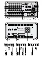
33 Ein-/Ausschalter POWER
34 Endstufenausgang für den Lautsprecheran-
schluß, siehe Abb. 3 – 5
(5 x 6,3-mm-Klinke, Ausgänge A + B jeweils par-
allelgeschaltet)
35 Netzkabel zum Anschluß an eine Steckdose
(230 V~/50 Hz)
36 Lüfter; kühlt die Elektronik, sobald das Gerät ein-
geschaltet ist
2
Hinweise für den sicheren Gebrauch
Dieses Gerät entspricht der Richtlinie für elektro-
magnetische Verträglichkeit 89/336/EWG und der
Niederspannungsrichtlinie 73/23/EWG.
Beachten Sie auch unbedingt die folgenden Punkte:
●
Das Gerät ist nur zur Verwendung im Innenbe-
reich geeignet. Schützen Sie es vor Tropf- und
Spritzwasser, hoher Luftfeuchtigkeit und Hitze
(zulässiger Einsatztemperaturbereich 0 – 40 °C).
●
Die in dem Gerät entstehende Wärme muß durch
den Lüfter (36) abgegeben werden. Decken Sie
darum keine der Lüftungsöffnungen auf der Gerä-
terückseite ab.
●
Stecken Sie nichts durch die Lüftungsöffnungen!
Dabei kann es zu einem elektrischen Schlag kom-
men.
●
Nehmen Sie das Gerät nicht in Betrieb bzw. zie-
hen Sie sofort den Netzstecker aus der Steck-
dose, wenn:
1. sichtbare Schäden am Gerät oder an der Netz-
anschlußleitung vorhanden sind,
2. nach einem Sturz oder ähnlichem der Verdacht
auf einen Defekt besteht,
3. Funktionsstörungen auftreten.
Lassen Sie das Gerät in jedem Fall in einer Fach-
werkstatt reparieren.
●
Eine beschädigte Netzanschlußleitung darf nur
durch den Hersteller oder eine autorisierte Fach-
werkstatt ersetzt werden.
●
Ziehen Sie den Netzstecker nie an der Zuleitung
aus der Steckdose.
●
Verwenden Sie für die Reinigung nur ein trocke-
nes, weiches Tuch, auf keinen Fall Chemikalien
oder Wasser.
●
Wird das Gerät zweckentfremdet, falsch bedient
oder nicht fachgerecht repariert, kann für eventu-
elle Schäden keine Haftung übernommen werden.
●
Soll das Gerät endgültig aus dem Betrieb genom-
men werden, übergeben Sie es zur Entsorgung
einem örtlichen Recyclingbetrieb.
3
Einsatzmöglichkeiten
Der Power Mixer PMX-150DSP ist eine Kombination
aus einem 7-Kanal-Mischpult und einer 2 x 100-W-
Endstufe. Er geeignet sich besonders für Musiker
und den Einsatz auf der Bühne. An die Eingangs-
kanäle lassen sich Geräte mit Line-Ausgang (Instru-
ment, CD-Spieler, Tape-Deck etc.) und Mikrofone
(auch phantomgespeiste) anschließen und auf eine
Signalsumme sowie auf einen Monitorweg mischen.
Achtung! Das Gerät wird mit lebensgefährlicher
Netzspannung (230 V~) versorgt. Neh-
men Sie deshalb nie selbst Eingriffe im
Gerät vor. Durch unsachgemäßes Vor-
gehen besteht die Gefahr eines elektri-
schen Schlages. Außerdem erlischt
beim Öffnen des Gerätes jeglicher
Garantieanspruch.
Vorsicht! Die Gesamtimpedanz aller ange-
schlossenen Lautsprecher darf im
Stereobetrieb pro Kanal 4
Ω
und im
Brückenbetrieb 8
Ω
nicht unterschrei-
ten, sonst kann die Endstufe beschä-
digt werden. Siehe auch Kapitel 4.3.
20 Jack MONITOR (6.3 mm jack, unbal.) for the out-
put of the mono monitor way, also see item
3 control MON and item 29 control MONITOR
21 Output MAIN (6.3 mm jack, unbal.) for the master
signal
22 Effect selector switch PROGRAM SELECT
23 Button to switch on the internal effect processor
with LED ON indication
24 LEDs CLIP light if an input is overloaded – turn
back the corresponding control LEVEL (6)
25 POWER LED
green unit is in operation
red
protective circuit responds:
for 3 seconds after switching on (switch-
on delay) or in case of a defect, e. g. a
short circuit at the power amplifier outputs
OUTPUT (34)
26 Switch PHANTOM POWER to activate the 48 V
phantom power,
also see item 9 input MIC
27 Level indication (2 x 5 LEDs) for the master sig-
nal [internal power amplifier and output MAIN
(21)]
28 7-band graphic equalizer for the master signal
[internal power amplifier and output MAIN (21)]
29 Level control MONITOR for the mono monitor
way [output MONTOR (20)]
30 Mode selection switch for the internal power
amplifier
L+R
BRIDGE the stereo power amplifier is
bridged and can deliver higher
power to a mono speaker
STEREO
the power amplifier is in stereo
operation
31 Level control MAIN for the master signal [internal
power amplifier and output MAIN (21)]
32 Control TAPE IN to add the signal of the input
TAPE (18) to the master signal (is not fed to the
monitor way)
1.2
Rear panel
33 POWER switch
34 Power amplifier output for the speaker connec-
tion, see figs. 3 to 5
(5 x 6.3 mm jack, outputs A + B each connected
in parallel)
35 Mains cable for the connection to a mains socket
(230 V~/50 Hz)
36 Fan; cools the electronics as soon as the unit is
switched on
2
Safety Notes
The unit corresponds to the directive for electro-
magnetic compatibility 89/336/EEC and to the low
voltage directive 73/23/EEC.
The following items must be observed in any case:
●
The unit is suitable for indoor use only. Protect it
against dripping water and splash water, high air
humidity and heat (admissible ambient tempera-
ture range: 0 – 40 °C).
●
The heat generated within the unit must be carried
off by the fan (36). Therefore, do not cover the air
vents of the housing with any objects.
●
Do not insert anything through the air vents! This
may result in an electric shock.
●
Do not operate unit or immediately disconnect the
plug from the mains socket
1. if there is visible damage to the unit or to the
mains cable,
2. if a defect might have occurred after the unit
was dropped or suffered a similar accident,
3. if malfunctions occur.
In any case the unit must be repaired by skilled
personnel.
●
A damaged mains cable must be replaced by the
manufacturer or by skilled personnel only.
●
Never pull the mains cable to disconnect the
mains plug from the socket.
●
For cleaning only use a dry, soft cloth, by no
means chemicals or water.
●
If the unit is used for other purposes than originally
intended, if it is not correctly operated or not re-
paired by skilled personnel, no liability for any
damage will be accepted.
●
If the unit is to be put out of operation definitively,
take it to a local recycling plant for disposal.
●
Important for U. K. Customers!
The wires in this mains lead are coloured in ac-
cordance with the following code:
green/yellow = earth
blue = neutral
brown = live
As the colours of the wires in the mains lead of this
appliance may not correspond with the coloured
markings identifying the terminals in your plug,
proceed as follows:
1. The wire which is coloured green and yellow
must be connected to the terminal in the plug
which is marked with the letter E or by the earth
symbol
, or coloured green or green and
yellow.
2. The wire which is coloured blue must be con-
nected to the terminal which is marked with the
letter N or coloured black.
3. The wire which is coloured brown must be con-
nected to the terminal which is marked with the
letter L or coloured red.
Warning - This appliance must be earthed.
Attention! The unit is supplied with hazardous
mains voltage (230 V~). Leave serv-
icing to skilled personnel only. Inexpert
handling may cause an electric shock
hazard. Furthermore, any guarantee
claim will expire if the unit has been
opened.
Caution! The total impedance of all connected
speakers in stereo operation must
not be lower than 4
Ω
per channel
and in bridge operation not lower
than 8
Ω
, otherwise the power ampli-
fier can be damaged. Also see chap-
ter 4.3.
5
GB
D
A
CH


