Error! Use the Home tab to apply Überschrift 1 to the text that you want to appear here.
Image Engineering
Error! Use the Home tab to apply Titel to the text that you want to appear here.
Seite
5
von
11
2.4 Connection of CAN-USB board / control panel PCB
Connect the small green CAN-USB adapter board via the two red connectors to the backside of the iQ-LED
board (picture flag 2). You can fix the adapter board with a screw to the main board if needed. If you use more
than one iQ-LED in a row, you still need one CAN-USB adapter on the first iQ-LED in the row.
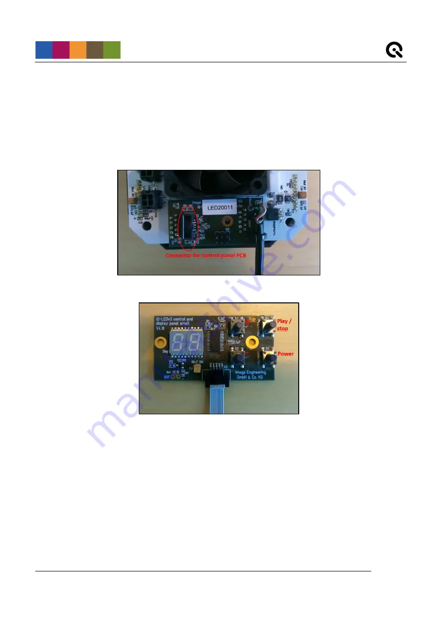
The control panel board (if needed) must be connected to the CAN-USB adapter board via the ribbon connector
cable.
Connected CAN-USB adapter board
Control panel PCB
On the control panel PCB, it is possible to set different light settings for the iQ-LED´s (without a connection to a
PC):
o
with the “+” and “-“ buttons you can switch between 44 saved illuminants
o
numerical display to show the storage of the illuminants
o
with the play and stop button you can start and stop a saved light sequence with different
illuminates (it is possible to save one sequence)
o
with the power button, you can turn on and off the light
To create and store illuminants (or sequences) on your device, please follow the instructions in the SW manual.


