11
Exhausting cooker hood
The equipment is constructed in accordance with
European Standards and the requirements included in
the following Directives: 73/23 EEC (electric-low tension
safety), 89/336 EEC (electromagnetic compatibility),
93/68 EEC (EC marking regulations).
Before installing and/or using the hood:
• read all the instructions thoroughly;
• be sure that the ceiling structure is suitable for the
installation of this heavy equipment
• make sure that the voltage (V) and frequency (Hz)
ratings indicated on the plate inside the hood unit
correspond to the ones available in the installation
place.
• At least two people are needed for the installation
procedure, which it is advisable to entrust to competent
technicians.
PRESENTATION
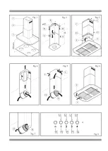
The equipment (Pic. 1) is made of the following items:
1) Telescopic inside structure (Picture 1-1)
2) External telescopic chimney (Picture 1-2)
3) Cooker hood module (Picture 1-3)
1. INSTALLATION
Read the instruction manual before installing and/or
using the hood.
Range hoods and other cooking fume extractors
may adversely affect the safe operation of appliances
burning gas or other fuels (including those in other
rooms) due to the back flow of combustion gases.
These gases can potentially result in carbon monoxide
poisoning. After installation of a range hood or other
cooking fume extractor, the operation of flued gas
should be tested by a competent person to ensure that
back flow of combustion gases does not occur.
The unit must be fitted at a distance of at least 65 cm.
from the cooking hob. It must not be mounted above
cookers fitted with top radiant plate. The stale air must
be discharged in a manner complying with current
regulations.
All fastenings are supplied.
Installation of the structure to the ceiling (Picture 2)
1) Adjust the height H of the telescopic structure by
employing the screws as in Picture 2-A, considering
that the cooker hood Module height is mm. 350 and
that minimum distance between the equipment and the
cooktop is mm. 700 as described in Picture 1.
2) Fix to the ceiling the telescopic structure by means of
the screw anchors you have been provided
(Picture 2-B).
Installation of the telescopic chimney (Picture 3).
3) Put in and fix the upper flue chimney to the telescopic
structure by means of the screws as in Picture 3-C.
4) Put completely in the lower flue chimney upwards
and hold it up temporarily, screwing in the screws as
in Picture 3-D. Installation of the cooker hood Module
(Picture 3)
5) Put in the cooker hood module on the telescopic
structure and fix the screws as in Picture 3-F.
6) At this stage of the operation you can take off the
screws employed in Picture 3-D to hold on the lower flue
chimney and let it go down holding on the cooker hood
module.
This cooker hood can be employed as exhausting or
filtering (when provided for).
The cooker hood can be employed as filtering only
when the upper chimney is provided with holes for the
evacuation of the purified air.
Exhausting (external evacuation). Kitchen smokes are
driven outside through a flue joined to the exhaust pipe
flue connector (Picture 4). Install this flue after completing
what’s described in the previous point 2 of this section.
This pipe must not under any circumstances be
connected to cooker, boiler or burner exhaust pipes, etc.
If the hood is operated in suction function whilst stoves,
gas cookers, fuel-fed boilers. etc. are being used,
ventilation from outdoors must be provided, since
the cooker hood removes from the environment the
necessary air for a correct combustion.
The charcoal filters must not be fitted to the cooker hood
in exhausting version.
Filtering (inside recycling). Smokes pass through the
activated charcoal filters (Picture 5-H) to be cleaned and
recycled in the kitchen environment through the holes
from which the purified air will come out. These holes
have to be free and communicating with the kitchen
environment (Picture 5-L).
In this case you should not install the exhaust pipe.
2. ELECTRICAL CONNECTIONS
This equipment must be connected to a grounding plant.
Two types of electrical connection can be used:
a) Using a standard plug to be connected to the power
cable and inserted in a mains socket which must be
accessible (so that the plug can be disconnected when
servicing is carried out).
b) By means of a fixed mains connection, fitting a bipolar
switch with contacts opening of at least 3 mm. The
ground connection (yellow-green wire) must not be
interrupted. Refer to the plate inside the hood for the
mains voltage and frequency ratings.
For stationary appliances permanently connected to
the fixed wiring, compliance with this requirement is
considered to be met if the instruction concerning
disconnection incorporated in the fixed wiring is in
accordance with AS/NZS 3000
Refer to the plate inside the hood for the mains voltage
and frequency ratings.
INSTALLATION, OPERATING AND MAINTENANCE INSTRUCTIONS FOR
RANGE HOODS DESIGNED FOR WALL FITTING 230 Vac • 50 Hz
Содержание X301ISL Series
Страница 1: ...INSTRUCTION MANUAL INSTRUCTION MANUAL X301ISL SERIES ISLAND HOOD X301ISL SERIES ISLAND HOOD ...
Страница 2: ......
Страница 7: ......
Страница 8: ...INSTALLATION 4 ...
Страница 12: ......


