background image

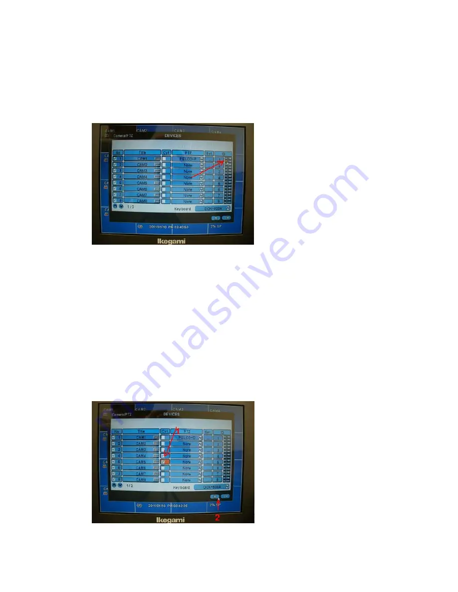
9.When you need to change the ID number for controlling    PCS-400P series 

camera, click and set the red arrow shown point(+,- , ^ , also can be set) 


The camera side PCS-400P series ID set up proceeding is shown on page 

11 to 13 of PCS-400P Series Dome Installation & Set-up Guide. (Unit table A 

should be used for PELCO-D 2400, S1: 0 , S2:1,for ID number 1) 

10. Through above setting when you do not want to show the controlled picture, 

chick marked as below red arrow 1 pointed. The display screen is covert but can 

be recorded as you like. Click the red arrow 2 pointed, set-up data is memorized. 


Содержание PCS-418

Страница 1: ...85 A Green wire RS 485 B Coax Video signal 2 Also connect above RS 485 wire and Video cable BNC to rear side of SDR 500 Series as page 9 of User s Manual SDR 500 Series The Video out of SDR 500 series...

Страница 2: ...Login Screen displayed Click Key board Icon which shown by red arrow 5 Next Screen displayed as follows please enter PASS WORD 1 1 1 1 The detail information for above Item 4 and Item5 are shown page...

Страница 3: ...mple In this case also the PCS 400P Series Protocol should be set up PELCO D with S3 switch page 11 of PCS 400P Series Dome Installation Set up Guide S3 1 ON 2 OFF 3 ON 7 OFF for PELCO D 2400 The came...

Страница 4: ...orange color point Then below screen is displayed red arrow shown point click and select the Baud Rate Pelco D 2400 shall selected 2400bps in this case Data bit Stop Bit Parity Menu Tour Pattern setti...

Страница 5: ...ng is shown on page 11 to 13 of PCS 400P Series Dome Installation Set up Guide Unit table A should be used for PELCO D 2400 S1 0 S2 1 for ID number 1 10 Through above setting when you do not want to s...

Страница 6: ...11 Next screen appeared as below Click Exit 12 Next screen is shown the Blue Dome camera icon this means CAM1 is set PTZ Icon on screen are shown on page52 5 1 Viewing of User s Manual SDR 500 Series...

Страница 7: ...me camera icon picture on multi screen display then full screen for PTZ camera is displayed Pan Tilt Control shown on page53 and 54 5 15 Pan Tilt Control of User s Manual SDR 500 Series If following t...

Страница 8: ...een Click the PTZ on SET UP MENU Then blue dome camera icon picture is shown bottom of screen as below shown picture this means the PCS 400P series camera can be control from SDR 500series DVR Please...

Страница 9: ...wn page 53 of User s Manual You can control manually PAN TILT ZOOM IN OUT FOCUS IRIS is auto iris only for PCS 400P series as shown key pad by clicking 13 4 When click the Menu on Key pad screen you c...

Страница 10: ...ion Fig 1 1 Number 10 17 Cursor shift 2 Number 7 Close this Key pad screen 3 Number 3 Select Enter PASS WORD A A A A 4 Number 8 Save preset 5 Number 9 Start the Tour for PCS 400P on RUN selected on sc...

Страница 11: ...r is stop and reset the Starting point When you need start again for Tour back the 13 5 and repeat again this procedure The PCS 400P MENU Structure Introduction is shown on page 14 to page 31 of PCS 4...

Отзывы: