background image

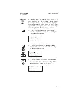
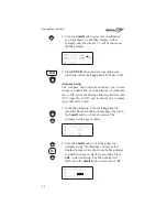
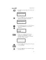
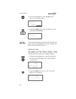
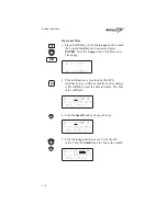
4. Press SEL to activate editing. The first Nav field

will flash.

ete SLE

00:20

2.00

“¼¼

Dtk 353

48.0nm

5. Turn the Small knob to select the desired Nav

information to be displayed in that field.

GroundSp 100 kts

2.00

“¼¼

Dtk 353

48.0nm

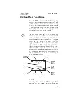
6. Turn the Large knob to move to the next field to

edit. Turn the Small knob to select the Nav
information.

GroundSp 100 kts

Trk 353

Dtk 353

48.0nm

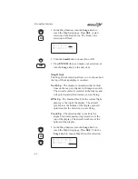
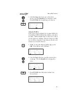
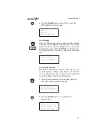
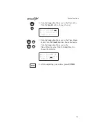
7. When you are finished selecting Nav page

information, press ENTER. You will be
prompted to decide if you want to include this
page in the Autonav scrolling.

Nav Page 2 in

Autonav Pages?

Yes

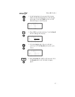
9. Turn the Small knob to choose between Yes and

No. Press ENTER.

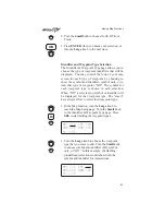
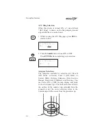
10. Turn the Small knob to view another Nav page

and repeat steps 4-9.

SEL

ENTER

ENTER

System Functions

101

Содержание Apollo GX55

Страница 1: ...Apollo GX55 GPS Receiver User s Guide 560 0962 00 June 1997 ...

Страница 2: ...rrow Inc All rights reserved Printed in the U S A II Morrow Inc Consumer Products Division 2345 Turner Road S E Salem OR 97302 U S A Toll Free 800 525 6726 Canada Toll Free 800 654 3415 International 503 391 3411 FAX 503 364 2138 Visit our web page at http www iimorrow com Send comments about this manual by email to techpubs iim ups com II MORROW V I S I O N A R Y T H I N K I N G T O D A Y ...

Страница 3: ... level of performance and reliability that aviation users require The Apollo GX55 sets a precedent that will be the standard that all other avionics will be compared to The Apollo GX55 is a full featured GPS receiver You can be confident in knowing that you are the owner of the state of the art in aviation navigation and communication Our products are built to last and to satisfy your navigation n...

Страница 4: ...ing Information To receive additional copies of the Apollo GX55 manuals order the following part numbers User s Guide 560 0962 xx User s Guide Binder 3 4 560 9002 xx Installation Manual 560 0960 xx GX55 Quick Reference 561 0237 xx History of Revisions ii ...

Страница 5: ...cause harmful interference and 2 this device must accept any interference received including interference that may cause undesired operation This equipment generates uses and can radiate radio frequency energy and if not installed and used in accordance with the instructions may cause harmful interference to radio communications However there is no guarantee that interference will not occur in a p...

Страница 6: ... of keys hard keys and smart keys The hard key is a permanent key on the right side of the front panel The NAV key example shown here is a hard key The smart keys are five small keys below the display The key label is shown above the key on the display and may change depending on the function you are using Press the key below the label to access the function Text in a display example with an under...

Страница 7: ...rge Knobs 3 Keys 3 Hard Keys 3 Smart Keys 4 Map Function Smart Keys 5 Apollo GX55 Features 6 Getting Started the First Time 7 Power On 7 Seed Position 7 Entering a Seed Position 8 Change Reference Waypoint 9 Change Lat Lon Reference Position 9 Checking GPS Signal Strength 11 Entering a Destination Waypoint 13 Using the Nearest Waypoint Function 13 Using the Direct To Function 14 Waypoint Search Me...

Страница 8: ...iation Indicator CDI and Distance Off Track 22 Desired Track Dtk 24 Leg FROM TO Distance 24 Track Trk Angle 25 Track Angle Error Tae 25 Ground Speed GS 25 Minimum Safe Altitude MSA 26 Minimum En Route Safe Altitude MESA 26 Flight Time 27 Time UTC 27 Estimated Time of Arrival ETA 27 Nearest Waypoint Search 28 Starting Nearest Waypoint Search 28 Searching Around a Reference Waypoint 29 Setting Runwa...

Страница 9: ...Waypoint Database 49 Waypoint Information 49 Available Waypoint Information 49 Getting Information about a Waypoint 51 Nearest Waypoint Search 54 Create User Waypoint by Lat Lon 55 Create User Waypoint by Radial Distance 56 Delete User Waypoint 59 Modify User Waypoint 60 Creating Waypoint Comments 61 Deleting Waypoint Comments 62 Flight Plan Functions 63 Flight Plan Pages 63 Reaching the Flight Pl...

Страница 10: ...ivate 77 Rev Activate 78 Reactivate 78 Rename 78 Copy Plan 79 Estimate Ground Speed 79 Clear Waypoints 80 Reverse Flight Plan 80 Estimated Fuel Flow 80 Delete Plan 81 Hold 81 Holding Patterns 82 Continue 84 Destination Waypoint Information 85 Flight Plan Comments 86 Saving an Active Flight Plan 87 Moving Map Functions 89 Full Screen Map 89 Controls 89 Map Scale 90 Map and Nav Info 91 Table of Cont...

Страница 11: ...able Pages and Autonav Pages 100 Customizing Navigation Pages 100 Selecting Autonav Pages 102 Restoring Default Nav Pages 102 Setting Units 103 Magnetic Variation 104 Flight Timer Trigger 105 Direct To Entry Options 106 CDI Scaling 107 System Information 108 Software Version 108 Test Display 109 Owner Information 109 Date and Time 112 GPS Sensor 114 Satellite Search Status 115 GPS Date and Time Pa...

Страница 12: ...get a RAIM not available message 122 What Does A Raim Alarm Mean 122 How Often Do Satellite Failures Occur 122 Start Up Displays 125 Owner Message 125 Memory Tests 125 Software Memory Test 125 Non Volatile RAM Tests 126 User Database Memory Failure 126 Miscellaneous NVRAM Memory Failure 127 Database Test 127 Database Message 128 IFR Output Tests 128 External Annunciator Lamp Tests 131 Screen Test ...

Страница 13: ...Battery Replacement 144 If You Have A Problem 144 If You Are Unable To Correct The Problem 144 Flight Simulator 147 About the Flight Simulator 147 Removing and Replacing the Apollo GX55 148 Starting the Flight Simulation 148 Flight Simulator Operations 150 Glossary of Navigation Terms 151 Index 159 Table of Contents xi ...

Страница 14: ...Notes Table of Contents xii ...

Страница 15: ...Bs intersections and special use airspaces that makes the Apollo GX55 an encyclopedia of aviation The database can be updated by simply changing the removable data card in the front of the unit The database can also include 500 custom waypoints created by the user Thirty flight plans can be saved with up to twenty legs for setting up custom tailored routes The detailed Navigation information displ...

Страница 16: ...ss during daylight operation Relative Bearing Indicator The Relative Bearing Indicator is an arrow next to the Bearing value that indicates an approximate bearing to a waypoint or airspace relative to the aircraft s current track when your current ground speed is more than 5 knots The following illustration describes the bearing range for each arrow M N O P Q R T 23º to 67º 68º to 112º 113º to 157...

Страница 17: ...depending on the function Keys There are two types of keys that allow you access to the functions in your Apollo GX55 permanent hard keys and displayed smart keys Seven back lighted permanent keys are used to reach the functions or perform other operations of the GX55 The smart key labels are shown on the bottom of the display There are two categories of smart keys those available for the Map func...

Страница 18: ...c map display DIRECT TO The DIRECT TO key is used to define a direct course from your present position to a waypoint Press once to select a waypoint Press twice to enter an OBS desired track ENTER The ENTER key enters and saves the information flashing on the display If the ENTER key is not pressed after editing any changes made are not saved Smart Keys MSG Message Press the MSG key to reach the M...

Страница 19: ... key to control the display of the waypoint type There are three selections possible waypoint identifier and location symbol location symbol only and off Pressing the smart key subsequent times will control which selection is made A solid reversed waypoint type annunciator above the smart key means the waypoint identifier and location symbol will both be displayed A bold outline of the waypoint ty...

Страница 20: ...tings nm and km distance knots Clock and Countdown Timer Auto Manual Magnetic Variation Settings Direct To Nav Function Parallel Track Nearest Waypoint Search Internal Database of Airports VORs NDBs Intersections Frequencies and Airport Info GPS Receiver Performance Specifications 8 Channel Parallel GPS Receiver Certified TSO C129 Class A2 for En Route and Terminal Operation Physical Specification...

Страница 21: ...atabase information shows on the display for several seconds and then will go into the Navigation function Seed Position Each time the Apollo GX55 is switched on it must locate satellites in the sky to acquire signals before determining a position fix in a complex process involving lengthy mathematical operations Without a seed position and the current UTC time and date this process can take 10 mi...

Страница 22: ...hoice of SEL to change the Seed Position or ENTER to accept the previous position If you don t do anything the Apollo GX55 will continue normally You can also press ENTER to accept the current position though this is not required Ppos 2 3nm 130 To Nrst Wpt SLE Ent OK SEL Chnge 2 Press SEL to change the Seed Position 3 The current Reference Position will be displayed and the Chg prompt will flash P...

Страница 23: ...aracter of the waypoint name 4 When you have entered the waypoint name press ENTER Change Lat Lon Reference Position 1 Set the latitude and longitude coordinates near to your current position After setting the Reference Waypoint the first character of the Reference Position Lat Lon will flash Ppos 44 54 46N 122 59 69W Ref Wpt Chg ENTER ENTER AIRPORT SALEM CITY OR USA SLE Waypoint Type Airport show...

Страница 24: ...mall knob Ppos 44 54 46N 122 59 69W 3 When you have entered the Lat Lon position press ENTER 4 After entering the Seed Position you will be prompted next to clear the active flight plan Choose Yes or No with the Small knob Press ENTER to continue normal operations Clear Active Flight Plan NO ENTER ENTER Getting Started the First Time 10 ...

Страница 25: ...lable in the GPS Sensor part of the System section of this manual see page 114 1 Press SYS and turn the Large knob to display the GPS Sensor function Press ENTER Gps Sensor Press ENTER 2 The GPS Health page is shown if GPS information is received The GPS number and dimension 2D 3D or no position number of healthy and number of visible satellites are shown GPS 3D Position Healthy Sats 24 Visible Sa...

Страница 26: ...e signal the status will display as DATA SV16 Status SRCH ele 11 Sig 000 Azimuth 039 SV24 Status DATA ele 74 Sig 123 Azimuth 132 Note The GPS antenna must be able to see each satellite it is tracking If a satellite is shaded by the wing or fuselage during a turn it may temporarily lose track of that satellite If this happens or if the geometry of the satellites available is poor Nav information wi...

Страница 27: ...t function is displayed with the distance and bearing from your present position to the indicated waypoint See page 53 in the Waypoint section for a more complete description of using the Nearest Waypoint function Near 1 to PPos SLE AIRPORT Brg 352 5 4nm 2 Turn the Large knob to view the different waypoint types Near 1 to PPos UBG VOR Brg 344 26 6nm 3 Turn the Small knob to view the 20 nearest way...

Страница 28: ...ect To key The waypoint type will flash VOR CVO SALEM CITY OR USA 2 Turn the Small knob to select the waypoint type You may select AIRPORT VOR NDB INT or USER For instance with AIRPORT indicated as the type of destination waypoint only airports show on the display as you select identifier characters AIRPORT SLE SALEM city OR USA 3 Turn the Large knob clockwise cw one position to the waypoint ident...

Страница 29: ...unction and show information based on a direct route from your present position to the Direct To destination waypoint ete aHIO 00 12 0 000 Brg 346 35 2nm Waypoint Search Methods The Apollo GX55 uses a unique flexible search engine that allows you to quickly and easily select the desired waypoint from its massive database You can not only search for waypoints character by character but also by sele...

Страница 30: ... Turning the Large knob moves the cursor flashing character Turning the Small knob changes the first character and shows waypoints starting with the first character Turn the Small knob to show a K AIRPORT 5VD KADOKA city SD USA 2 Turn the Large knob to the third character and then turn the Small knob to select an L AIRPORT 09C KALAMAZOO city dup MI USA 3 Now press the SEL key Note that the entire ...

Страница 31: ...FCA KALISPELL city dup MT USA Viewing Duplicate City or Facility Names While performing Waypoint Identifier selection you may see the word dup on the bottom line This means that there more than one of the displayed city or facility name The same technique described above can be used to search for duplicate city and facility names Getting Started the First Time 17 ...

Страница 32: ... INFO to view information about the TO waypoint HIO AIRPORT PORTLAND city OR USA 2 Turn the Small knob to view the available information about the TO waypoint See page 51 for more details about waypoint information HIO ATIS 127 65 UNIC 123 00 TWR 119 30 HIO 12 30 6600ft Hard ILS Lighted 3 Press INFO again to return to the previous display INFO INFO Getting Started the First Time 18 ...

Страница 33: ...gation function displays The navigation information displays and sequencing rate are user programmable See the Nav info section of the System Functions chapter see page 99 The Large knob will select the higher level Nav functions Nav pages Parallel Track Offset GPS Position Countdown Timer and the FROM TO NEXT Waypoints The Small knob will look at the pages available for each function a diamond wi...

Страница 34: ...ying the Nav Home Page or one of its sub pages Ete aEUG 00 22 1 10 Brg 082 74nmY 2 Stop Autonav rotation by pressing any key or turning either knob TO WPT FROM WPT North Track Angle Error Tae Present Position BRG TRK DTK Distance Off Track or Cross Track Deviation Course DTK TAE Difference between Track and Desired Track Bearing Direction to waypoint Course Desired Track between specific waypoints...

Страница 35: ...Brg Bearing is the angle from your present position to the TO waypoint Bearing is shown from 0 to 359 degrees in one degree increments Bearing is computed using the magnetic variation at the Present Position The Bearing value will be dashed if the FROM or TO waypoints are blank or the GPS receiver does not have a valid position Estimated Time Enroute Label Waypoint Indentifier Bearing Value Estima...

Страница 36: ...Course Deviation Indicator CDI and Distance Off Track The triangle symbol referenced to a bar graph shows your position relative to being on course When the bar graph is to the right of the triangle you must fly right to return on course the bar graph indicates you are off course to the left Fly the aircraft in the direction of the bar graph to return on course ete aSLE 00 37 4 005 Brg 173 42 4nm ...

Страница 37: ...lay opposite from the triangle symbol shows the distance off track The numbered values of Cross Track Error are in the direction you are off course If the numbers are on the left side fly right to return on course The displayed value ranges are 0 000 to 0 999 nm with 0 001 nm resolution 1 0 to 9 99 nm with 0 01 nm resolution and 10 0 to 99 9 nm with 0 1 nm resolution ete aSLE 00 37 0 006 Brg 173 4...

Страница 38: ...rrent TO waypoint is shown as a value on the bottom right of the Desired Track DTK Nav page but does not show any label In this example the leg FROM TO distance is 42 4 nm The nautical mile units are 0 00 to 9 99 nm at 0 01 nm resolution 10 0 to 99 9 nm at 0 1 nm resolution and 100 to 9999 nm at one nm resolution Kilometer units are 0 00 to 99 99 km at 0 01 km resolution 100 0 to 999 9 km at 0 1 k...

Страница 39: ...rror is shown from 0 to 359 degrees in one degree increments Track Angle Error is computed using the magnetic variation at the Present Position The Track Angle Error value will be dashed if the FROM or TO waypoints are blank if the GPS receiver does not have a valid position or if ground speed is less than 5 knots Ground Speed GS Ground Speed is the measure of your progress over the ground not air...

Страница 40: ...EF the higher MEF will be used The MEF on the sectional chart is derived by taking the altitude of the highest obstruction within the grid rounded up to the next 100 feet and adding 300 feet For example if the highest obstruction is 4 728 feet the MEF would show as 5 100 feet eta aSLE 01 23 MinSafeA 7200 EnrtSafeA 16800 Minimum En Route Safe Altitude MESA Minimum En Route Safe Altitude is the high...

Страница 41: ...the Flight Timer is not started the value will be replaced with dashes The Flight Timer Trigger options are set in the System Functions see page 105 FT00 07 Time UTC Time is displayed using the 24 hour clock based on Universal Coordinated Time Units are hours and minutes 00 00 to 23 59 13 15 UTC Estimated Time of Arrival ETA The ETA is to the current TO waypoint at the current Ground Speed from th...

Страница 42: ... lighting and surface type Press INFO while viewing a Nearest waypoint for more information about that waypoint Starting Nearest Waypoint Search 1 Press the NRST key Turn the Large knob to display the waypoint type and options Airport VOR NDB Intersection INT User USER Choose Reference Waypoint Runway Limits and Special Use Airspace Near 1 to PPos SLE AIRPORT Brg 352 2 4nm 2 Turn the Small knob to...

Страница 43: ...to view Choose Waypoint to Search Around and press ENTER Choose Wpt to Search Around Press ENT 2 The waypoint type will flash Turn the Small knob to choose Airport VOR NDB Intersection INT or User waypoint type VOR PDX PORTLAND facil OR USA 3 Turn the Large knob to the waypoint identifier name The first character of the identifier will flash Turn the Small knob to change characters Turn the Large ...

Страница 44: ...b to view the nearest 20 waypoints of the selected type to the selected reference waypoint Turn the Large knob to change waypoint types Note The last viewed Nearest Waypoint will be the waypoint shown the next time you want to insert a waypoint For instance if you press NRST and look at PDX the next time you want to insert a waypoint into a flight plan PDX will show first ENTER Navigation Basics 3...

Страница 45: ...e will flash Turn the Small knob to select the minimum runway length you want considered Choosing a length of 0 feet means you will accept any runway length Choosing a runway length for instance of 5 000 feet will not show an available airport with a runway length less than 5 000 feet either for a Nearest Waypoint or as an airport on the Map display Runway Limits HARD SOFT WATER Ft 3500 Lit No 3 T...

Страница 46: ...the first ten airspaces within 100 miles are displayed While searching for airspaces the keys and knobs are disabled and the following display will appear Searching for Airspaces The information for airspaces includes name position in the list 1 10 type and proximity Proximity is indicated as either Soon Outside Inside Above Below or Close Criteria for airspace searches is set in the System functi...

Страница 47: ...t from your current FROM TO course from 0 1 to 20 0 nm You must have FROM and TO waypoints defined Parallel Track cannot be activated if you set a course using Direct To Transitions between future flight plan legs cannot be greater than 120 degrees You select to place Parallel Track In Use or to put it on Standby choose Left or Right of the current course and the offset distance The PTK annunciato...

Страница 48: ...n and distance values are what you want press ENTER If you want to change the direction or distance turn the Large knob to choose the direction or distance fields Parallel Track Offset Use RIGHT 12 4nm 3 After turning the Large knob to the direction field turn the Small knob to choose Left or Right Parallel Track Offset Standby LEFT 12 4nm 4 Turn the Large knob to the distance field Turn the Small...

Страница 49: ...alue than a larger one A PDOP value of 3 will provide a more reliable position fix than a value of 7 In the Navigation function turn the Large knob to display the GPS Position page The PDOP value is shown in the lower right corner 1 9 is shown here GPS InUse 44 10 11N PDOP 123015 84W 1 9 Countdown Timer The Countdown Timer allows you to set a timer that will alert you when it expires with a flashi...

Страница 50: ... MSG key to note the time out message Arc Assist The Arc Assist function will help you to navigate along an arc Arc Assist can be used as a user defined arc to avoid special use airspaces or for conducting aerial searches using increasingly larger circles The Arc Assist page shows the direction of the arc left or right the reference waypoint identifier the desired track for the arc and the distanc...

Страница 51: ...f UBG vor Press ENT or SEL 2 Press SEL Choose another waypoint using the Large and Small knobs VOR CVO CORVALLIS facil OR USA 3 Select the Arc direction with the Small knob Left Arc dtk 171 ref CVO vor Rad 005 14 0nm Rght Arc dtk 351 ref CVO vor Rad 005 14 0nm 4 Press ENTER to accept the selections and start navigating Note The DTK on the Arc Assist page is the no wind heading to hold the distance...

Страница 52: ...an and vice versa Select waypoints from the database including the following types airport VOR NDB Intersection INT and User defined USER You can search for waypoints by facility identifier waypoint type or by facility name From SLE arpt To UBG vor Next HIO arpt Creating FROM TO NEXT Waypoints ABCD A Set the FROM Waypoint 1 While in the Navigation function turn the Large knob to view the FROM TO N...

Страница 53: ... Small knob AIRPORT AAF APALACHIOCOLA city FL USA 4 Turn the Large knob to the first character of the waypoint name The first character of the waypoint name will flash Turn the Small knob to select the desired character AIRPORT EAA EAGLE city AK USA 5 Turn the Large knob clockwise one click to move to the next character Turn the Small knob to select the desired character Continue to select additio...

Страница 54: ...ou have selected the desired waypoint From EUG arpt To ______ Next ______ B Set the TO Waypoint 1 Press SEL and move to the TO waypoint with the Large knob The insert Ins choice will flash Press ENTER and then select the TO waypoint as you did for the FROM waypoint From EUG arpt To Ins Next ______ 2 After selecting a TO waypoint press ENTER From EUG arpt To SLE Next ______ SEL ENTER ENTER ENTER Na...

Страница 55: ...t Ins 2 After selecting a NEXT waypoint press ENTER From EUG arpt To SLE arpt Next HIO arpt D Editing FROM TO NEXT Waypoints 1 While in the Navigation function turn the Large knob to view the FROM TO NEXT page Press SEL to start editing From EUG arpt To SLE arpt Next Chg arpt 2 Turn the Large knob to select the FROM TO or NEXT waypoint field to edit From EUG arpt To Chg arpt Next HIO arpt SEL ENTE...

Страница 56: ...previous examples Placing the TO Waypoint on Hold 1 Press SEL and move to the TO designation with the Large knob You can also place the To waypoint on hold by pressing the external WPT SEQ button when it is installed The HOLD annunciator will light when it is installed From EUG arpt Hold SLE arpt Next HIO arpt 2 Turn the Small knob to choose Hold or To Placing the TO waypoint on Hold suspends wayp...

Страница 57: ...hen you press DIRECT TO the default waypoint shown will be the current TO waypoint in the Nav or Flight Plan functions or the waypoint displayed in the Database or Info functions Function DIRECT TO Waypoint Default Nav Current TO waypoint Database Displayed waypoint Flight Plan Displayed leg TO waypoint Info Displayed waypoint You can always select a different Direct To waypoint but the default is...

Страница 58: ...irect To Examples The following three examples provide some of the more common ways that you can use the powerful Direct To function Center the CDI After changing your course to avoid weather an obstacle or being directed you may need to reset your course to center your CDI to continue navigating to your intended TO waypoint D ENTER Present Position SLE MMV Leg 1 Leg 2 CDI EUG CDI Before After Dir...

Страница 59: ...entered as you are on course Enter a New Waypoint into a Flight Plan While on a flight plan you may want to temporarily go to a new waypoint to look at something or you may be directed by ATC By using Direct To you can add this new waypoint into your existing flight plan This way your flight plan is essentially unchanged but you were still able to react quickly to new conditions HIO SLE MMV DLS Le...

Страница 60: ...5 37 8nm arpt arpt 2 Press DIRECT TO Select the desired waypoint using the Large and Small knobs AIRPORT MMV MC MINNVILLE city OR USA 3 Press ENTER The Nav function will now be displayed with your new TO waypoint MMV ete aMMV 00 20 0 011 Brg 321 15 6nm 4 Check your active flight plan pages Press FPL Turn the Small knob if necessary Note that your current leg now shows a direct flight to MMV direct...

Страница 61: ...nob one click cw to check the next leg Note that your flight plan continues to HIO as your original plan did You have inserted a new leg using the Direct To function MMV to HIO 2 003 22 2nm arpt arpt Navigation Basics 47 ...

Страница 62: ... entered Waypoint sequencing at the TO waypoint is automatically inhibited placed on Hold 1 Press DIRECT TO twice The first character of the Desired Track value will flash Turn the Small knob to change the value OBS DTK 100 to MMV brg 000 dtk 000 2 Turn the Large knob to move to the next character Turn the Small knob to change the value OBS DTK 115 to MMV brg 000 dtk 000 3 Press ENTER when the des...

Страница 63: ...nges VORs Non directional beacons NDBs En route intersections INTs User created USERs Available Waypoint Information The following information is available for each waypoint type Use the waypoint INFO function to get this information as the Introduction describes in Waypoint Information AIRPORT Waypoint Information Bearing and distance from present position Airport type Airport elevation Fuel avai...

Страница 64: ...tion Operating frequency Lat Lon coordinates Name Identifier INT Waypoint Information Country Bearing and distance from present position Bearing from present position Lat Lon coordinates USER Waypoint Information Bearing and distance from present position Distance from present position Lat Lon coordinates User entered Runway Length User entered Identifier User entered Waypoint comments User entere...

Страница 65: ...ific features See Waypoint Search Methods on page 15 for more details on searching for waypoints 1 Press the DB key Turn the Large knob to view the Access Database page and then press ENTER AIRPORT AAF APALACHICOLA city FL USA 2 The waypoint type field will flash Choose Airport VOR NDB Intersection or User defined with the Small knob AIRPORT AAF APALACHICOLA city FL USA 3 Turn the Large knob to th...

Страница 66: ...the facility name As you turn the Large knob to the city facility field PDX AIRPORT PORTLAND city OR USA Multiple facilities or cities with the same name will have a dup between the city facility and state on the bottom row PDX AIRPORT PORTLAND city dup OR USA 6 Press SEL so the whole name flashes Turn the Small knob to view the waypoints with the same city or facility name TTD AIRPORT PORTLAND ci...

Страница 67: ...7 Press INFO to view information about the selected waypoint AIRPORT TTD PORTLAND TROUTDA city dup OR USA 9 Press ENTER or INFO to leave the function ENTER INFO INFO Waypoint Database 53 ...

Страница 68: ...re details on using Nearest Waypoint Search Starting Nearest Waypoint Search 1 Press the NRST key 2 Turn the Large knob to display the waypoint type and options Airport VOR NDB Intersection INT User waypoints Choose Reference Waypoint Runway Limits and Special Use Airspace 3 Turn the Small knob to display the nearest 20 waypoints The waypoints must be within 600 miles of your present position The ...

Страница 69: ...ER Create User Wpt by Lat Lon Press ENT 2 The first character of the waypoint name will flash Turn the Small knob to select the desired character 000 USER 44 24 29N Rwlen 122 51 52W 0000 3 Turn the Large knob clockwise one click to move to the next character Turn the Small knob to select the desired character Continue to select the needed characters for the Waypoint Name Latitude Longitude and Run...

Страница 70: ... the DB soft key Turn the Large knob to view the Create User Wpt By Rad Dis page and then press ENTER Create User Wpt by Radial Dist Press ENT 2 The first character of the radial will flash Ref Wpt AAF 000 0 000 0nm 3 Select the Reference Waypoint Turn the Large knob ccw one click to select the waypoint identifier which will be replaced by the change prompt Chg Press ENTER to change the waypoint i...

Страница 71: ...fier After the reference waypoint name is chosen press ENTER Ref Wpt SLE 000 0 000 0nm 5 The first character of the radial will flash Now select the needed characters for the Radial and Distance Turn the Small knob to change characters Turn the Large knob to move to the next character Ref Wpt SLE 040 0 012 0nm 6 Press ENTER when you have finished entering the waypoint information You will be promp...

Страница 72: ...e You can also adjust Lat Lon and add the Runway Length Changing the Lat Lon will alter the radial distance value so you shouldn t change it unless you need to Press ENTER when you are finished CABIN USER 44 10 96N Rwlen 121 43 35W 0000 ENTER Waypoint Database 58 ...

Страница 73: ...Delete User Waypoint page Delete User Wpt Press ENT 3 Press ENTER The waypoint identifier will flash Turn the Small knob to view the User waypoints Find Wpt to Del CABIN user Press ENT 4 When the waypoint to delete is displayed press ENTER ENTER ENTER DB Waypoint Database 59 ...

Страница 74: ...r of the waypoint identifier will flash CABIN USER 44 10 96N Rwlen 121 43 35W 0000 4 Turn the Small knob to select the desired character Turn the Large knob clockwise one click to move to the next character HABIN USER 44 10 96N Rwlen 121 43 35W 0000 5 Turn the Small knob to select the desired character Continue using the Small knob to change characters and the Large knob to move to the desired cha...

Страница 75: ...ll knob to the Waypoint Comment page and press SEL Waypoint Comment Press SEL 2 The first character flashes on a blank screen You can add 16 characters per line for three lines Upper case letters numbers and spaces are allowed 3 Turn the Large and Small knobs to edit the comment Press ENTER to save the comment 900FT TOWER 14NW NW OF AIRPORT STAY EAST OF TWR ENTER INFO SEL Waypoint Database 61 ...

Страница 76: ...nt 5 used Press ENT 2 Press ENTER to view the waypoint comments The first waypoint comment page will show the waypoint identifier waypoint type and a portion of the comment The waypoint identifier will flash CABIN USER 900FT TOWER 14NW NW OF AIRPORT 3 Turn the Small knob to view the available waypoint comments Press ENTER to delete the displayed comment ENTER ENTER DB Waypoint Database 62 ...

Страница 77: ...o the leg number means that the displayed leg is in the Active flight plan Two asterisks mean that the displayed leg is the active leg and shows the current FROM and TO waypoints which are being used for navigation Flight Plan Pages The first page of each flight plan is the Name Page The Name Page displays the flight plan name total distance and the destination waypoint Distance is displayed as 0 ...

Страница 78: ...tive with asterisks This name cannot be changed in the Active page Active 259nm Dest Wpt PDT Active Creating a Flight Plan The basic steps for creating a flight plan include entering the plan name and inserting waypoints You may then view flight plan information activate the plan and use the other options WPT2 WPT1 Departure WPT Present Position WPT3 WPT4 WPT5 Leg 1 Leg 2 Leg 3 Leg 4 Flight Plan F...

Страница 79: ...me 3 Turn the Small knob to select the first flight plan name character R_______ Enter a New Plan Name 4 Turn the Large knob clockwise one click to move to the next character position Turn the Small knob to select the next name character You can have up to eight characters in the flight plan name ROUTE 2 Enter a New Plan Name SEL FPL Flight Plan Functions 65 ...

Страница 80: ...osition is ready for a FROM waypoint to insert ______ to ______ 1 Press SEL to Edit Leg 7 Press SEL to insert a FROM waypoint The Ins prompt will flash Press ENTER to insert a FROM waypoint Ins to ______ 1 ___ __ _nm ____ ____ 8 Turn the Small knob to select the waypoint type Turn the Large knob to the waypoint identifier Turn the Small knob to select the first character of the waypoint identifier...

Страница 81: ...ver EUG to Ins 1 ___ __ _nm ____ ____ 11 Repeat steps 7 10 for the remaining waypoints in your flight plan SLE to Ins 2 ___ __ _nm ____ ____ 12 Press SEL when your flight plan is complete Turn the Small knob to view the legs in your flight plan Press SEL while viewing a flight plan leg page to make changes Press SEL and then turn the Small knob while viewing the flight plan name page to activate o...

Страница 82: ...isects the angle between the two legs determines when the flight plan sequences to the next leg In the example below the dashed line describes the area where the flight plan will sequence from Leg 1 to Leg 2 and for the last waypoint Wpt 3 WPT 2 WPT 3 Leg 1 Leg 2 WPT 1 FROM FROM TO Angle Bisector Angle Bisector FROM TO Flight Plan Functions 68 ...

Страница 83: ...ht plan leg press SEL The From waypoint field will flash Chg to SLE 1 353 48 0nm arpt arpt 2 Turn the Large knob clockwise two clicks to choose the third line for selection The line will flash EUG to SLE 1 353 48 0nm arpt arpt 3 Turn the Small knob to choose from the list of available leg information options The options are described on the following pages EUG to SLE 1 353 48 0nm Leg ETE 00 30 4 P...

Страница 84: ...eed is used for the calculation EUG to SLE 1 353 48 0nm ETA 17 27 Leg ETE The Estimated Time En Route between the displayed FROM and TO waypoints Leg ETE requires an actual ground speed of more than 20 knots If there is no valid ETA for the leg dashes will replace the value EUG to SLE 1 353 48 0nm Leg ETE 00 27 Leg ETE Leg ETE is the same as ETE except that Estimated Ground Speed is used for the c...

Страница 85: ...stimated Ground Speed on page 79 for more details EUG to SLE 1 353 48 0nm Leg ETE 00 24 Fuel To Fuel shows the amount of fuel required to get from the FROM waypoint to the TO waypoint for an inactive plan or from the present position to the TO waypoint for the Active flight plan See Estimated Ground Speed on page 79 for more details EUG to SLE 1 353 48 0nm Fuel To 32usg In the Active flight plan t...

Страница 86: ...If the leg page displayed is the currently active leg of the Active flight plan and a Direct To waypoint has been entered the From waypoint will say Direct The leg just prior to the currently active leg displays the leg as if the Direct waypoint did not exist After sequencing the Direct disappears and the currently active leg once again displays the waypoint identifier See page 43 for more details...

Страница 87: ...an be inserted before an existing waypoint if at least one valid waypoint exists in the database Inserting a new waypoint into the Active flight plan before or after the current TO waypoint does not affect the currently active leg Inserting a new waypoint into the active leg s TO waypoint will immediately change navigation to the new TO waypoint Del An existing waypoint can be deleted if it is not...

Страница 88: ...n the Flight Plan function turn the Large knob to a flight plan and then use the Small knob to display the leg of the plan that you want to edit HIO to TTD 3 070 23 0nm arpt arpt 2 Press SEL The FROM waypoint will flash with the Chg prompt Turn the Large knob to the desired waypoint HIO to Chg 3 070 23 0nm arpt arpt 3 Press ENTER This takes you into the waypoint database Use the Large and Small kn...

Страница 89: ...knob if necessary to the waypoint you want changed HIO to Chg 3 067 75 0nm arpt arpt 3 If another option was last used turn the Small knob to choose Ins HIO to Ins 3 067 75 0nm arpt arpt 5 Press ENTER Use the Large and Small knobs to select the desired waypoint AIRPORT TTD PORTLAND city OR USA 6 After selecting the waypoint name press ENTER HIO to TTD 3 070 23 0nm arpt arpt ENTER SEL ENTER Flight ...

Страница 90: ... 23 0nm arpt arpt 3 Turn the Small knob to choose Del HIO to Del 3 070 23 0nm arpt arpt 4 Press ENTER The waypoint will be deleted Each flight plan leg will shift back to replace the deleted leg i e after deleting leg 3 leg 4 will then become leg 3 HIO to DLS 3 067 75 0nm arpt arpt SLE HIO MMV TTD Leg 1 Leg 2 Leg 3 Leg 4 DLS EUG Leg 5 Leg 6 SLE HIO MMV Leg 1 Leg 2 Leg 3 DLS EUG Leg 5 Before Deleti...

Страница 91: ...If you have gone past a given leg the next appropriate leg will be activated In the Flight Plan function turn the Large knob to view the available flight plans Only Inactive plans may be Activated Route 2 259nm Dest Wpt PDT Activate When you Activate a flight plan the Inactive flight plan is copied to the Active plan Any changes made to the Active plan will have no effect on the original Inactive ...

Страница 92: ...eactivate Press ENTER when the Reactivate option is displayed to reset the active leg to leg 1 and allow waypoint sequencing Only used for the Active plan Route 2 259nm Dest Wpt PDT Reactivate Rename Pressing ENTER when the Rename Plan option is displayed lets you rename the flight plan Duplicate names are not allowed Only used for Inactive plans Route 2 259nm Dest Wpt PDT Rename Plan Flight Plan ...

Страница 93: ...T Copy Plan 2 Turn the Small knob to select the flight plan you want to copy the flight plan into Press ENTER Route 2 259nm Copy Plan 9 Copy Plan Estimated Ground Speed While viewing a leg in an Active flight plan pressing ENTER when the Est Gr Speed option is displayed This allows you to enter an estimated ground speed value to be used in estimating some leg info options such as estimated fuel fl...

Страница 94: ...g ENTER when the Est Fuel Flow option is displayed allows you to enter an estimated fuel usage value to be used in estimating one of the leg info options Route 2 259nm Dest Wpt PDT Est Fuel Flow The estimated fuel flow can be selected from 0000 to 9999 units per hour The units may be set in the System function see page 103 Pressing ENTER saves the entered value if the value entered is less than or...

Страница 95: ...is option is not displayed Route 2 259nm Dest Wpt PDT Delete Plan Hold The Hold option is available for the Active flight plan when the flight plan status is Active waypoint sequencing allowed This function is used while viewing the Name Page Hold allows you to overfly the Active plan s current TO waypoint without sequencing When sequencing is started again normal operation continues So if your ai...

Страница 96: ...ing is suspended the OBS HLD annunciator is lit or suspend sequencing by pressing the OBS HLD button 2 Second after crossing the waypoint establish the desired inbound course to the waypoint by pressing DIRECT TO twice or pressing ENTER for the Set OBS Course message Select the inbound course with the Small and Large knobs then press ENTER 3 Enter the holding pattern by the most appropriate entry ...

Страница 97: ...lected inbound course and through the waypoint The CDI will indicate fly left if the aircraft is to the right of the desired track with reference to the selected inbound course The CDI will indicate fly right if the aircraft is to the left of the desired track with reference to the selected inbound course As with traditional VOR navigation these indications are always related to the aircraft posit...

Страница 98: ...Holding waypoint sequencing is not allowed Pressing ENTER when this option is displayed restarts the Active flight plan and enables waypoint sequencing 1 In the Flight Plan function turn the Large knob to display the Name Page Active 259nm Dest Wpt PDT Holding HIO NEXT UBG TO 3S2 FROM P e r p e n d i c u l a r t o 0 2 0 020 TO Side FROM Side If sequencing is enabled on the TO side of a line perpen...

Страница 99: ...t PDT Active Destination Waypoint Information Normal waypoint information about the destination waypoint can be viewed by pressing INFO when the Plan Name Page is displayed This is the same as pressing INFO to view information about a TO waypoint except that the Plan Comment page is available by turning the Small knob PDT AIRPORT Public elev 1493ft SEL ENTER Flight Plan Functions 85 ...

Страница 100: ...e one 1 While viewing the desired flight plan press INFO Turn the Small knob to reach the Comment page Waypoint Comment Press SEL 3 Press SEL Turn the Small knob to select the first character _ 4 Turn the Large knob clockwise one click to move to the next character position Turn the Small knob to select the next comment character GOOD RESTAURANT 5 After selecting the waypoint name press ENTER ENTE...

Страница 101: ...eated 1 Press FPL to reach the Flight Plan function Turn the Large knob ccw one click to display the Flight Plan creation page Press SEL to Create a New Flight Plan 2 Press SEL and then use the Large and Small knobs to enter a new plan name After entering the name press ENTER PLAN 9__ Enter a New Plan Name 3 Press ENTER a second time or turn the Small knob twice to return to the Inactive Flight Pl...

Страница 102: ...ctive flight plan from the list of flight plans with the Small knob The flight plan name will flash Press ENTER PLAN 9 0 0nm Copy Active Copy Plan 6 Your new flight plan now has the contents of the Active flight plan copied into it Your Active flight plan is not affected PLAN 9 204nm Dest Wpt PDX Inactive SEL ENTER ENTER Flight Plan Functions 88 ...

Страница 103: ...er of the display The TO waypoint identifier is shown in reversed text on the upper left corner The bearing from your current position to the TO waypoint is shown on the upper right corner The map scale is shown in the lower left corner The distance from the current position to the TO waypoint is shown in the lower right corner A 5 nm ATC Ring can be drawn around airports that have a control tower...

Страница 104: ...nt location A thin outline around the waypoint type means that it is turned off and no information for that waypoint type will be displayed on the map Map Scale The Map Scaling is controlled by turning the Small knob while viewing the map The map scale value shown is the distance from the top point of the airplane icon to the top of the screen Map scale choices in nautical miles are 0 1 0 2 0 5 1 ...

Страница 105: ...up functions are provided on three pages The map setup function allows you to select the route line map orientation map scale for viewing identifiers waypoint types that will be displayed airspace type and special use airspaces Route Line A Route Line can be drawn for the current and next leg of the active route when the selection is turned on TO Waypoint Identifier Cross Track Error Distance Dire...

Страница 106: ...aligned with magnetic north The aircraft symbol is centered in the display and will point towards the direction you are flying DTK Up The Desired Track for the current flight plan leg is the top of the display The aircraft symbol is at the bottom of the display and will point towards the direction you are flying Track Up The direction that your aircraft is aligned vertically and moving towards is ...

Страница 107: ...each selection When Off is selected no symbol or identifier will be displayed for that waypoint type The smart keys always allow to select their waypoint type 1 In the Map function turn the Large knob to reach the Map Setup page Turn the Small knob to the Identifier Waypoint Type page Press SEL to start editing the waypoint types APT ID INT ID VOR ÂID NDB ÁID Usr ÀID 2 Turn the Large knob to choos...

Страница 108: ...and time buffers turn ATC rings On or Off and to choose the Airspace types that will be used 1 In the Map function Turn the Large knob to reach the Route Line Map Orient page then turn the Small knob two clicks clockwise The Airspace Setup page is shown Airspace Setup Map ON Alerts ON 2 Turn the Small knob to view the pages for Airspace Setup On this page you may select whether Airspaces are shown...

Страница 109: ...ntervals Altitude values are from 0 to 9900 feet in 100 foot intervals Time values are from 0 to 20 minutes in one minute intervals 1 While viewing the Airspace Buffer page press SEL The distance value will flash Airspace Buffers Dist Alt Time 2nm 500 10min 2 Turn the Large knob to select the desired value to change Turn the Small knob to change the value Airspace Buffers Dist Alt Time 2nm 500 10m...

Страница 110: ...n 5 nm ATC Rings Map On Airspace Selections The Airspaces available for selection are Class B Off Outer or Sector Class C Off Outer or Sector MOA Training Unknown Alert Caution Danger Restricted Prohibited and Warning You may select ON or OFF for map display and alerts for each Airspace type The Outer selection refers to the outline of the outside ring extended from the ground on up The sector sel...

Страница 111: ...Off Alert Off 2 Press SEL to activate selection Turn the Small knob to change the selection Class B Airspace Map Sector Alert Off 3 Turn the Large knob to move to the next selection Turn the Small knob to select your choice Class B Airspace Map Sector Alert Outer 4 Press ENTER after making the selection Turn the Small knob to view the other Airspace pages SEL ENTER Moving Map Functions 97 ...

Страница 112: ...Notes Moving Map Functions 98 ...

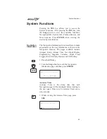
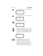
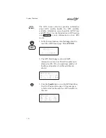
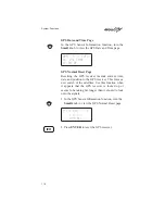
Страница 113: ...the Navigation function The pages available include Airspace Setup Autonav Time Nav Mode Display Programming Magnetic Variation Flight Timer Trigger Direct To Entry Option and CDI Scaling 1 Press the SYS key 2 Turn the Large knob to reach the Navigation Information page and then press ENTER Navigation Info Press ENTER Autonav Time Autonav Time is the delay time that each Navigation page will be di...

Страница 114: ...grammable basic navigation pages and the selection of pages used in the Autonav function All basic Nav pages are programmable except the first home page Customizing Navigation Pages 1 Press the SYS key Turn the Large knob to reach the Navigation Information page and then press ENTER 2 Turn the Large knob to reach Nav Mode Display and Autonav Pages Nav Mode Display Programmable and Autonav Pages 3 ...

Страница 115: ...ext field to edit Turn the Small knob to select the Nav information GroundSp 100 kts Trk 353 Dtk 353 48 0nm 7 When you are finished selecting Nav page information press ENTER You will be prompted to decide if you want to include this page in the Autonav scrolling Nav Page 2 in Autonav Pages Yes 9 Turn the Small knob to choose between Yes and No Press ENTER 10 Turn the Small knob to view another Na...

Страница 116: ...to choose between Yes and No Nav Page 4 in Autonav Pages Yes 3 Press ENTER Restoring Default Nav Pages 1 While viewing the Nav Mode Display Pages turn the Small knob to reach the Restoring Default Nav Pages display Press ENTER to Restore Default Nav Pages 2 Press ENTER to delete any changes you have made in the Nav display pages and revert to the original default pages SEL ENTER ENTER ENTER System...

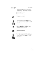
Страница 117: ...able and Autonav Pages 2 Turn the Small knob to reach a programmable Nav page ete SLE 00 20 2 00 Dtk 353 48 0nm 3 Press SEL to start field selection Turn the Large knob to the desired field ete SLE 00 20 2 00 Dtk 353 48 0nm 4 Turn the Small knob to select the field with different units Press ENTER to save the changes Press SEL to stop editing and ignore any changes ete SLE 00 20 2 00 Dtk 353 89 10...

Страница 118: ...he Large knob to the Magnetic Variation page and then press SEL Mag Variation Auto 18 E SEL to Edit 3 Turn the Small knob to select Auto or Manual Magnetic Variation and then press ENTER Mag Variation Manual 18 E 4 If you selected Manual Magnetic Variation turn the Large knob to move to the variation value field Select the variation value with the Small knob Mag Variation Manual 19 E SEL ENTER Sys...

Страница 119: ...e flight timer trigger speed The flight timer may be set to start at power up or when the ground speed exceeds from 10 to 500 knots The default factory setting is 60 knots The feature may also be turned off 1 In the Navigation section of the System function turn the Large knob to reach the Flight Timer Trigger page Press SEL Flight Timer Trigger At 60 kts 2 Turn the Small knob to select the speed ...

Страница 120: ... Direct To waypoint will be inserted in the Active flight plan and all of the other waypoints will be deleted from the Active flight plan With the Never Clears Direct To option the Direct To waypoint is inserted before the current TO waypoint The May Clear option is useful for the pilot who uses the Direct To function for the majority of flight planning and doesn t want to be bothered with a stead...

Страница 121: ...I Scaling option allows you to select manual or automatic full scale deflection of the internal CDI Manual full scale deflection options include 0 30 nm 1 00 nm and 5 00 nm Automatic scaling will use 5 00 nm as the setting 1 In the Navigation section of the System function turn the Large knob to reach the CDI Scaling page and then press SEL CDI Scaling Automatic ªªªªª 5 00nm 2 Turn the Small knob ...

Страница 122: ...abase Version Display test Owner Info and Date and Time Software Version The Software Version function provides version information about the Apollo software serial number database GPS sensor display software 1 In the System Information section of the System function turn the Large knob to reach Software Version page Apollo GX55 SW Vers X X SN 1234567 2 Turn the Small knob cw one click to view the...

Страница 123: ... Pressing any key or turning any knob will cancel the test To Test Display Press ENTER Owner Information The Owner Information function allows the user to enter their Name Address City Phone and Aircraft As a security feature the user must enter a password to enable editing of the Owner Information 1 In the System function turn the Large knob to reach the Owner Information page Owner Name WILBUR W...

Страница 124: ... character to the right by turning the Large knob cw When you turn the Large knob the last character is erased to enforce secrecy of your password Enter owner Password ______ 5 Press ENTER when you finish entering the password If the entered password does not match the true password you will be given another chance You can cancel by pressing SEL If the entered password matches the screen flashes a...

Страница 125: ...ve to the next character to the right by turning the Large knob cw Press ENTER to save the information 8 Turn the Small knob to go to the next Owner Information page you want to edit 9 Press SEL to start editing 10 Select the characters with the Small knob and move to the next character to the right by turning the Large knob cw Press ENTER to save the information SEL ENTER SEL ENTER System Functio...

Страница 126: ...the GPS satellites and you will not usually need to change it Press SEL to reset the date and time The Day value will flash Date 03 MAR 97 Time 23 24 UTC SEL to Reset 4 Turn the Small knob to choose the day Date 24 MAR 97 Time 23 24 UTC SEL to Reset 5 Turn the Large knob to move to the Month value Turn the Small knob to choose the month Date 24 APR 97 Time 23 24 UTC SEL to Reset SEL ENTER SYS Syst...

Страница 127: ... SEL to Reset 7 Turn the Large knob to move to the Time Hours value Turn the Small knob to choose the hours Turn the Large knob to move to the Time Minutes value Turn the Small knob to choose the minutes Date 24 APR 97 Time 17 34 UTC SEL to Reset 8 After completing your entries press ENTER ENTER System Functions 113 ...

Страница 128: ... reach the GPS Sensor page Press ENTER GPS Sensor Press ENTER 2 The GPS Health page is shown if GPS information is received The GPS number and dimension 2D 3D or no position number of healthy and number of visible satellites are shown GPS 3D Position Healthy Sats 25 Visible Sats 8 Y 3 Turn the Small knob to view the GPS Satellites Used for Position fixes page SV means space vehicle which is the sa...

Страница 129: ...rength Sig The relative strength of the received signal from the satellite Azimuth an arc as measured clockwise from magnetic or true north Satellite Search Status SRCH Receiver is searching for the satellite ACQR receiver is acquiring the signal TRCK receiver has locked to the satellite s data sequence DATA receiver is locked and downloading data from the satellite Until data is received by the r...

Страница 130: ...e date and position to the GPS receiver This forces a new search of the satellites Use this function when it appears that the GPS receiver is locked up or seems to be taking far longer than it should to lock onto the signals 1 In the GPS Sensor Information function turn the Small knob to view the GPS Normal Reset page Press ENT to do a Normal GPS Reset 2 Press ENTER to reset the GPS receiver ENTER...

Страница 131: ...e position fix information for military applications In recent years commercial applications for the information provided by this system have steadily increased in the civilian sector Some of the more popular civilian uses of the system include surveying and position fix data recording for civil engineering applications and a broad range of marine aviation and terrestrial navigation applications W...

Страница 132: ...ts GPS position fix accuracy to about 100 meters although the relative position of the satellites to one another their elevation above the horizon and other factors can also affect accuracy of the position fix Under optimal conditions accuracy can improve to within 10 meters GPS position fix accuracy is not affected by atmospheric conditions GPS altitude is based on a mathematical model of the sha...

Страница 133: ... good satellite signals enough satellites in view and an acceptable geometric position of the available satellites Integrity is the ability of the GPS system to detect when its position may not be accurate due to bad or false satellite information GPS systems limited to VFR use must meet the exact same accuracy requirements as those authorized for IFR use Systems authorized for IFR use must also h...

Страница 134: ... FAF TSO C129 requires the RAIM alarm limit to be at least 2 0 nm for en route operations 1 0 nm for Terminal operations and 0 3 nm for Approach operations What are En Route Terminal and Approach Operations Approach RAIM or 0 3 nm alarm limit is provided from 2 0 nm inbound to the FAF until you cancel the Approach Active operation usually at the MAP Approach RAIM is provided only if an approach is...

Страница 135: ...y the time of day the location the receiver design the antenna mask angle and location and on the method of baro aiding The Apollo GX55 has been designed such that with an optimal 21 satellites in operation Approach RAIM availability should exceed 95 There are currently at the time this manual was published at least 24 satellites in operation however the Federal Navigation Radio Plan only guarante...

Страница 136: ... flag the navigation display as invalid If the Apollo GX55 is providing valid navigation data then it is still capable of providing good IFR navigation as long as the satellite data is good What Does A RAIM Alarm Mean A RAIM alarm means that the navigation data can not be trusted to be within the alarm limit A RAIM alarm means that the Apollo GX55 has determined that there is something wrong with ...

Страница 137: ...ts navigation solution When a satellite fails even if that failure is detected by an earth based monitoring station it can be some time before an uplink to that satellite can occur During that time there is no way for a GPS receiver to know that the information from that satellite is bad directly from that satellite s transmissions An integrity monitor such as RAIM when it is available protects yo...

Страница 138: ...Notes Introduction to GPS Navigation 124 ...

Страница 139: ... Owner Message If the owner name has been previously entered in System Mode this page with your name is displayed for three seconds No owner info screen is displayed if the user has not entered the owner data Property of II Morrow Inc Memory Tests Memory tests are preceded by the following two second display Starting Memory Tests Software Memory Test This is a checksum test of the code memory regi...

Страница 140: ...wered up Any tests which detect a failure reset the failed values Generally the non volatile RAM test pages are not displayed since in most cases the tests pass User Database Memory Failure User waypoint checksums exist for each User waypoint If the checksums do not match the User waypoint is deleted If this occurs any flight plan which references this user waypoint is also deleted In addition Use...

Страница 141: ...ellaneous NVRAM or EEPROM Memory Failure All other user input values which are held in non volatile RAM are checked for validity producing the following message if any of the values needed to be reset Memory Test Failure Press ENTER Database Test This checksum test compares the database checksum stored on the database card with the calculated database checksum Since this test may take several seco...

Страница 142: ...Morrow Press ENTER Database Message This page shows the database name and expiration date If the database has expired press ENTER to continue Americas Database Expires mm dd yy Version x xx IFR Output Tests A series of tests covering connections for IFR flight are tested if your Apollo GX55 has been installed and configured for IFR flight Starting IFR Output Tests After the completion of all tests...

Страница 143: ...ts and display screens are provided for CDI Full Right CDI Half Right CDI Centered CDI Full Left and CDI Half Left TO FROM Flag Output Tests The To From Flag outputs are tested next Each of the following displays is shown for three seconds during which the external To From flag should be driven as indicated by the display which is up to the user to verify TO FROM FLAG To To From Flag tests and dis...

Страница 144: ...Flagged Nav Valid and Super Flag tests and display screens are provided for the Flagged and Not Flagged conditions VDI Output Tests VDI Vertical Deviation Indicator outputs are tested next Each of the following displays is shown for two seconds during which the external VDI needle should be driven as indicated by the display which is up to the user to verify VDI Tests VDI Full Up VDI tests and dis...

Страница 145: ...are provided for the Flagged and Not Flagged conditions External Annunciator Lamp Tests The external lamp outputs are tested next The external lamps which are driven by the GXseries GPS Navigation Equipment include the message lamp VFR lamp parallel track lamp approach lamp and two extra lamps The lamps are all flashed on for one second and off for one second a total of three times during which it...

Страница 146: ...ch line of the display and all of the annunciators is run next preceded for two seconds by the following screen Starting Display Test The visual display incrementally lights groups of pixels on the electroluminescent display Start Up Displays 132 ...

Страница 147: ...old message list where they remain until the condition causing the message goes away Other messages are cleared from the message list as soon as they are viewed they don t become old messages The decision whether a new message becomes an old message after viewing is described for each individual case below in the List of Messages section The formats of all messages are the same if they are in the ...

Страница 148: ...New Messages Turn Large Knob For Old Msgs Y 2 Turn the Small knob to view each message Old Messages The Old Message page shows how many old messages are stored 1 Press MSG Turn the Large knob to switch between New and Old Messages 2 Old Messages Turn Large Knob For New Msgs Y 2 Turn the Small knob to view each message MSG MSG Message Function 134 ...

Страница 149: ...e Airspace Messages are unique in Message Mode in that they are the only messages which the INFO key is used to find out more information concerning the message Ceil 8000 msl Floor 800 msl Brg 0080T 58 4nm SOON This condition occurs when penetration of the airspace is within 10 minutes or user selected limit in System Mode Within 10 Min of GABBS CENTRAL MOA CLOSE This condition occurs when the air...

Страница 150: ...not Compute Nav Info GPS Self Test Failure If the GPS self test fails a message displays indicating the cause of the failure in four hexadecimal digits It becomes an old message after viewing GPS Self Test Failure 1FFF Service Needed GPS Sensor Lat Lon Failure When the GPS sensor cannot compute the latitude and longitude the following message displays It becomes an old message after viewing GPS Po...

Страница 151: ...m a warning is generated and Nav data will be flagged as invalid The current flight phase is displayed first either Terminal or En Route It becomes an old message after viewing Terminal GPS RAIM ALARM Position Error GPS HDOP Position Error When the HDOP for the GPS sensor exceeds current flight phase HDOP requirements a warning is generated and Nav data will be flagged as invalid The current fligh...

Страница 152: ...e after crossing the angle bisector In the example below WPT 2 is the TO waypoint When the aircraft crosses the dotted line WPT 3 will become the TO waypoint This form of the Arrival Alert is provided when not holding at the current TO waypoint In addition to the arrival waypoint identifier the next leg s desired track is shown when available otherwise it is dashed Arrival SLE Next Dtk 3210 WPT 2 ...

Страница 153: ...uces the chance of nuisance alerts The new waypoint bearing and desired track are provided This message does not become an old message after viewing Sequence Alert new wpt SLE Brg 073 Dtk 069 Auto OBS Crossing Holding Waypoint When a waypoint on hold is crossed to the From side the first time the following message is provided If you press ENTER the OBS Desired Track screen is displayed This messag...

Страница 154: ...n Memory Loss This message indicates that one or more flight plans had a checksum error This message is cleared after the message is viewed Flight Plan Memory Loss 1 Deleted User Memory Failure This message indicates that one or more user settings were not within valid limits at power up and needed to be reset This message is cleared after the message is viewed Memory Failure User Setups Have Been...

Страница 155: ...mes an old message after being viewed Turn the unit off Pull out the data card and reinsert it If the problem persists contact your dealer or the factory for service Database Invalid Check Data Card Manual Magnetic Variation This message indicates that magnetic variation is on a manual setting This occurs when the database is not valid or when the user selects manual magnetic variation in System M...

Страница 156: ...Voltage This message is generated when high battery voltage is detected It becomes an old message after being viewed Battery voltage is checked every 15 seconds The unit must be returned to the factory for service Continued operation is NOT recommended Internal Battery Failure Turn Off Unit Needs Srvc Countdown Timer Expired This message is generated when the Countdown Timer which must have been c...

Страница 157: ...e the problem fail contact your dealer or the factory weekdays from 8 00 A M until 5 00 P M Pacific time for technical assistance The II Morrow technical service staff will gladly assist you Please have the following information ready System configuration products antennas mounting locations etc Model No part number and serial number Software versions Description of the problem Efforts made to iso...

Страница 158: ...y The expected service life of this type of battery is from 5 to 10 years This is not a user replaceable item The lithium battery must be replaced by the factory an authorized dealer or service center If You Have A Problem Please read the instructions again for the desired function If You Are Unable To Correct The Problem Record as much information as possible such as where and when the problem oc...

Страница 159: ...unctions If using a wrong antenna faulty external antenna wiring or connections Contact your dealer to check the antenna and other wiring Search for nearest waypoints reveals too few or wrong types of waypoints Incorrect selection of waypoint types to show after search Check Airspace Setup function and verify that the desired waypoint type to search is ON see page 94 Check the Runway Limits for to...

Страница 160: ...display Runway Limits are set for a value that is too large Reset the Runway Limits value see page 31 Bearing distance values appear to be wrong A mistake may have been made in entering the Lat Lon position for a User waypoint or the wrong waypoint was selected Verify that the position of the User waypoint is accurate Check the FROM and TO waypoints Wrong bearing and track values Incorrect magneti...

Страница 161: ...n constant throughout the simulation The Apollo GX55 uses a simulated GPS sensor to provide position altitude speed and course information As no external sensors are connected while the simulation is running no information is displayed about external sensors The simulated altitude does not change while the Flight Simulator is running The Apollo GX55 uses the position of the first FROM waypoint in ...

Страница 162: ...our Apollo GX55 Connect the cable to a power supply that provides 10 to 40 VDC 1A or greater Attach the black wire to ground and red wire to positive A suitable power supply may be purchased at an electronics or auto supply retailer Starting the Flight Simulation The following procedure is used to start the flight simulation It is recommended that you have a data card properly inserted into the da...

Страница 163: ...nged in 100 ft increments Simulator Setups Gr Speed 170kts Altitude 4500ft 5 Press ENTER to enter the displayed ground speed and altitude values and start the flight simulation 6 You will prompted to use or clear the previous Flight Plan Turn the Small knob to choose Yes or No Press ENTER If you do nothing the Apollo GX55 will automatically retain the previous Flight Plan and switch to the Nav fun...

Страница 164: ...t To courses and inserting deleting changing waypoints in the Active flight plan The simulator is also useful for planning purposes you may create and edit flight plans in the comfort of your office or home Changes made to flight plans and waypoints while the simulator is running are retained when the Apollo GX55 is reinstalled in the aircraft Flight Simulator 150 ...

Страница 165: ...mation about weather and other conditions at an airport periodically updated when conditions change Autonav The function that allows you to set the GX55 to scroll automatically through selected navigation displays Azimuth an arc as measured clockwise from true or magnetic north B Bearing BRG The direction to any point usually measured in degrees relative to true or magnetic north C Circular Error ...

Страница 166: ...e of waypoints and waypoint information Users may add waypoints to this database Degree 1 360th of a circle Departure The first waypoint in the active route Desired Track DTK The desired course of navigation between a point of origin and a destination waypoint Destination The last waypoint in the active route Dilution of Precision DOP A merit value for the calculated position based on the geometri...

Страница 167: ...eographical location determined by either visual reference or by electronic navigation aids Flight Time Flight Time shows the elapsed time in hours and minutes 00 00 to 99 59 from departure If the Flight Timer is not started the value will be replaced with dashes The Flight Timer options are set in the System Functions see page 105 Flight Plan A series of two or more waypoints G GDOP Geometric Dil...

Страница 168: ...or Los Angeles International Airport is LAX Instrument Flight Rules IFR Intersection INT A point defined by any combination of courses radials or bearings of two or more navigational aids K Knot kt A unit of speed equal to one nautical mile per hour L Latitude Lat Any line circling the earth parallel to the equator measured in degrees minutes and seconds north and south of the equator LFAC Landing...

Страница 169: ...del of the earth used for the purpose of creating navigation charts and maps The Apollo GX55 uses the WGS84 map datum MESA Minimum Enroute Safe Altitude is the highest MSA for every point between the aircraft present position and the TO waypoint with a 5 nm buffer around the course Meter m A metric distance measurement equal to 39 37 inches Minute 1 60th of a degree MSA Minimum Safe Altitude The e...

Страница 170: ...or similar navigational aid beginning at the navigational aid and proceeding outward in a straight line RAIM Receiver Autonomous Integrity Monitoring A method of predicting possible system accuracy errors that may be caused by bad satellite data The RAIM algorithm requires that more satellites are available and usable than required for a normal GPS position fix Range RNG The distance from the pres...

Страница 171: ...ion at the Present Position Track Angle Error TAE The difference between the Desired Track and the Track Angle Dtk Trk Tae Track angle is computed using the magnetic variation at the Present Position TRU True outside air temperature True North Geographic north at the earth s north pole Tower TWR Airport tower communication frequency U UNICOM The radio frequencies assigned to aeronautical advisory ...

Страница 172: ... east west zones each six degrees wide in longitude V Very High Frequency Omnirange VOR A navigational aid that transmits signals such that a receiver can indicate its current radial or bearing from the transmitter VHF Very High Frequency The range of frequencies between 30 and 300 MHz W Waypoint A navigation fix used in area navigation and defined by latitude and longitude coordinates Glossary of...

Страница 173: ...ntinue flight plan 84 Controls 3 Conventions iv Copy flight plan 79 Countdown timer 35 142 Cross track distance 23 Current time 7 Customizing Nav pages 100 D Database expired 141 Database message 128 Database test 127 Date and Time 112 Delete flight plan 81 Description Cross track distance 23 Moving map 89 Nav display 21 Nav terms 20 To From switching 23 Waypoint 9 Desired track 24 Diamond 19 Dire...

Страница 174: ...0 Starting 148 Flight time 27 105 From 83 FROM waypoint 23 From To distance 24 From To Next 38 41 Fuel 71 G Glossary 151 GPS 116 117 Antenna 12 Azimuth 115 Elevation 115 Failure 136 Health 11 114 Introduction 117 Position 35 Reset 116 Satellite failure 122 Satellites 11 115 Sensor 114 Signal strength 11 115 Time 114 Ground speed 25 H Heat 144 History of Revisions ii Hold 33 42 81 Holding at To wpt...

Страница 175: ...o 50 Nearest waypoint 13 31 54 Nearest waypoint search 28 Non volatile RAM test 126 NVRAM 127 O OBS 48 139 Ordering Information ii Owner information 109 Owner message 125 P Parallel track 33 35 In Use 33 Standby 33 Part numbers ii Password 110 PDOP 35 Photocell 2 Power knob 3 Power Up 7 Programmable Nav pages 100 R RAIM 119 RAIM alarm 122 Range 22 Reactivate 78 Reference Waypoint 9 29 56 Relative ...

Страница 176: ...3 U Underline iv User database memory failure 126 User waypoint Create 55 56 Delete 59 Information 50 Modify 60 User waypoint info 50 UTC time 7 27 V VDI flag tests 131 VDI output tests 130 VOR Info 50 W Waypoint 118 Airport info 49 Arrival 138 Auto OBS crossing 139 Comments 61 Destination 13 85 FROM 38 Getting info 51 Information 18 49 Intersection info 50 Last used 30 NDB info 50 Nearest 13 Next...

Страница 177: ... Inc 2345 Turner Rd S E Salem OR 97302 U S A Phone 503 581 8101 800 525 6726 In Canada 800 654 3415 FAX 503 364 2138 http www iimorrow com Part 560 0962 00 June 1997 II MORROW V I S I O N A R Y T H I N K I N G T O D A Y ...

Отзывы: