127191-01B
5
IHP.us.com
Final Preparation
1. Replace any vermiculite and ember material if displaced. Refer to
Ember and Pan Material Placement
in owner’s manual.
2. Reinstall logs starting with the rear log, front logs, then remaining
top logs. Refer to
Log Placement
in owner’s manual.
3. Leak check gas control and any connections you’ve made before
operating appliance. Refer to
Gas Supply Hook-up
in owner’s manual.
4. Replace refractory access panel and volcanic stone.
5. Replace glass doors if previously installed. Refer to
Installing Optional
Glass Doors
in owner’s manual.
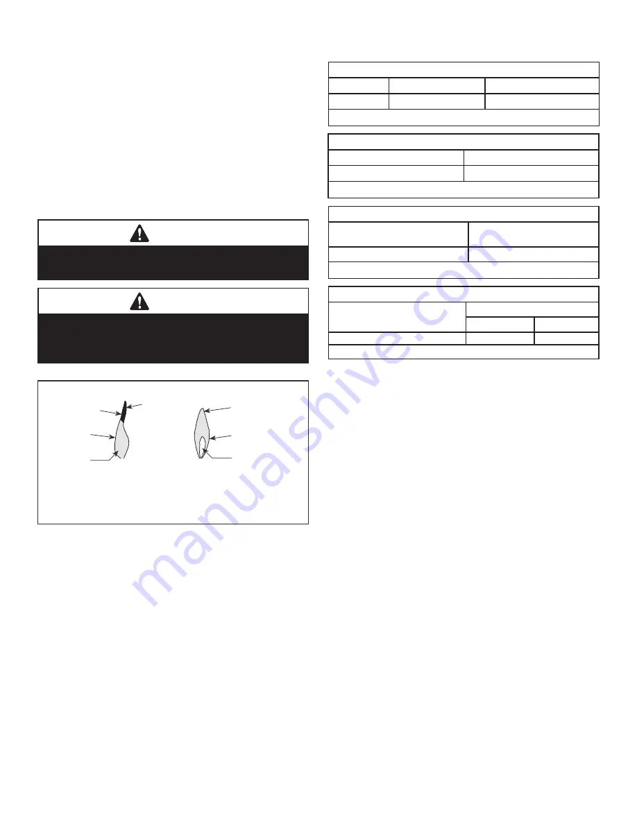
6. Using a manometer, test the inlet and manifold gas pressures.
Inspect for proper burner fl ame appearance
(see
Figure 11
).
The conversion is now complete. To operate your fi replace, refer to
Operating Fireplace
in your appliance owner’s manual.
WARNING
Test all gas piping and connections for leaks after
installation or servicing. Correct leaks at once.
WARNING
Never use an open fl ame to check for a leak. Apply
noncorrosive leak detection fl uid to all joints. Bubbles
forming show a leak. Correct all leaks at once.
Figure 11 - Inspect for Proper Burner Flame Appearance
No Blue Flame
Center
Soot at
Flame Tip
Dark Orange
Flame
IMPROPERLY
BURNING FLAME
Soot above
Flame Tip
No Soot at
Flame Tip
PROPERLY
BURNING FLAME
Semi-Transparent
Yellow Flame
Blue Flame
Center
REFERENCE INFORMATION
Inlet Gas Supply Pressure
Fuel #
Minimum
Maximum
Propane
11.0” WC (2.74 kPa)
13.0” WC (3.23 kPa)
Table 1
Manifold Gas Supply Pressure
Fuel #
Pressure
Propane Gas
10.0” WC / (2.49 kPa)
Table 2
Main Burner Orifi ce Sizes
Fireplace Model
Drill Size
Propane
BRT2332 and BRT2532
#54
Table 3
BTU Input
Models
Propane Gas / LP
High Rate
Low-rate
BRT2332 and BRT2532
25,000
n/a
Table 4
f i r e - p a r t s . c o m


