IHP F3772 Скачать руководство пользователя страница 2

2

NOTE: DIAGRAMS & ILLUSTRATIONS ARE NOT TO SCALE.

Figure 5

Figure 6

Figure 7

INSTRUCTIONS FOR INSTALLING LIGHTS BAFFLE

1.  Install light glass holder from old baffle onto new baffle.
2.  Install the lintel from the old baffle onto the new baffle by sliding lintel 

onto front edge of new baffle and bending tabs down (see Figures 4 

and 6).

3.  Remove the two screws on the top triangle shape cover (see Figure 

9) and screw the rear tab of the  new  baffle in the same location.

4.  Screw the baffle to the front using 3 screws shown in Figure 2.

Latches

Screws

2 Latches

Firebox 

Floor

IF UNIT IS TOP-VENTED, FIELD SERVICE IS COMPLETE.

NOTE: It is important to ensure proper log and or media placement 

per the manual when installing these units. Verify pilot flame is not 

obstructed.

Reference manual to test fire unit and verify proper operation.

IF THE UNIT IS REAR-VENTING, CONTINUE ON TO 

INSTRUCTIONS ON NEXT PAGE.

5.  Remove the lintel from the old baffle by bending tabs up (see Figure 

4), and sliding the Lintel off of the front edge of the baffle.

6.  Remove light glass holders from old baffle by removing four screws 

(see Figure 5).

7.  Change the pilot hood -

  Step 4a (see Page 4)

  Step 4b (see Page 4) 

8.  NOTE: Skip this step If the unit was installed without flue Restrictor. 

  Replace flue restrictor with the new restrictor assembly. Discard the 

existing restrictor. See Figures 11 and 12

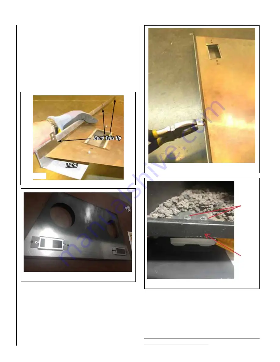
9.  Replace the existing door latches with the new ones provided in the 

kit  by removing the latches screws from the firebox floor. Discard the 

old latches (see Figure 7).

 Figure 4

f i r e - p a r t s . c o m

Содержание F3772

Страница 1: ...HWH 10 16X1 2 Typ AB Blk 4 ea Screw 10 16x 38 HWH B Blk 1 ea Pilot Hood 1 ea Rear Baffle Block off Plate 40 models only 1 ea Baffle 40 DVA w Lights 1 ea Baffle 45 DVA w Lights 1 ea Installation Instructions TOOLS REQUIRED 5 16 Socket Screw Pliers 4mm Allen Wrench Small Flat Screwdriver FIELD SERVICE UPGRADES SHALL ONLY BE COMPLETED BY A QUALIFIED SERVICE TECHNICIAN CAUTION SHARP EDGES WATCH YOUR F...

Страница 2: ...placement per the manual when installing these units Verify pilot flame is not obstructed Reference manual to test fire unit and verify proper operation IF THE UNIT IS REAR VENTING CONTINUE ON TO INSTRUCTIONS ON NEXT PAGE 5 Remove the lintel from the old baffle by bending tabs up see Figure 4 and sliding the Lintel off of the front edge of the baffle 6 Remove light glass holders from old baffle by...

Страница 3: ...ion in new baffle as shown in Figure 9 3 Install the bent Baffle Block Off Plate as shown in Figure 8 using the 2 screws provided in kit Figure 11 Vent restrictor installation Top vent Figure 12 Vent restrictor installation Rear vent Installation in top vent Put flap and wing if installed directed toward the rear of unit Installation in rear vent Install so flap and wing if installed will stay clo...

Страница 4: ...is complete with the installation of the Block Off Plate 4a Remove pilot head by pulling up firmly discard it and verify proper pilot gas setting For Natural gas units the orifice should be turned counter clockwise For Propane LP gas units the orifice should turned clockwise Some pilot orifices require a small flat standard screwdriver and somerequirea4mmallentypewrenchtorotatetheorifice in the pi...

Отзывы: