Содержание Odyssey BAYLOAMS20

Страница 1: ...ment observe all precautions in the literature and on the tags stickers and labels that are attached to the equipment August 2021 A AC CC C S SV VN N1 19 90 0B B E EN N Installation Guide Head Pressure Control Kit Odyssey Split System with Symbio Controls 13 to 25 Tons B BA AY YL LO OA AM MS S2 20 0 TTA156 180 201 240 251 300 TWA156 180 201 240 MOTOR ON OFF N O OK LINE 120 600VAC P N ICM334 LF MAD...

Страница 2: ...ar r p pr ro op pe er r P PP PE E f fo or r t th he e j jo ob b b be ei in ng g u un nd de er rt ta ak ke en n c co ou ul ld d r re es su ul lt t i in n d de ea at th h o or r s se er ri io ou us s i in nj ju ur ry y T Te ec ch hn ni ic ci ia an ns s i in n o or rd de er r t to o p pr ro ot te ec ct t t th he em ms se el lv ve es s f fr ro om m p po ot te en nt ti ia al l e el le ec ct tr ri ic ca...

Страница 3: ...an nd dl li in ng g e et tc c W Wh he er re e l lo oc ca al l r re eg gu ul la at ti io on ns s a ar re e m mo or re e s st tr ri in ng ge en nt t t th ha an n t th he es se e p po ol li ic ci ie es s t th ho os se e r re eg gu ul la at ti io on ns s s su up pe er rs se ed de e t th he es se e p po ol li ic ci ie es s N No on n T Tr ra an ne e p pe er rs so on nn ne el l s sh ho ou ul ld d a al lw...

Страница 4: ...s List 5 General Information 6 Disable Evaporator Defrost Control 6 Installation 7 Controller 7 Transducer and Tee 9 Wiring 9 Control Box Wiring 9 Controller Settings 15 Operation and Troubleshooting 17 Checkout Procedure 17 Table of Contents ...

Страница 5: ...dge Protector 5 4 Screw 8 32 X 1 25 Pan Head 6 4 Screw 10 16 X 50 Hex Head 7 1 Label Information BAYLOAMS20 8 2 Tee Pressure Tap 9 2 Bracket Support 10 2 Harness Low Ambient Kit SOV Item Number Quantity Description 11 1 Harness 2 Kits Jumper 12 1 Harness 24V UC Board to Loam 13 2 Harness Power 14 2 Transducer 15 2 Controller Low Ambient 16 1 Supplemental Wiring Diagram 17 1 Installation Guide 18 1...

Страница 6: ...rost Control I Im mp po or rt ta an nt t For proper operation of the low ambient head pressure control accessory in an Odyssey condenser the Evaporator Defrost Control EDC function MUST be disabled To disable the EDC navigate to the Utilities menu on the Symbio 700 user interface and change the configuration parameter Evaporator Defrost Control to Disabled The Symbio Service and Installation mobil...

Страница 7: ...d p pe er r N NF FP PA A 7 70 0E E t th ha at t a al ll l c ca ap pa ac ci it to or rs s h ha av ve e d di is sc ch ha ar rg ge ed d W WA AR RN NI IN NG G P Pr ro op pe er r F Fi ie el ld d W Wi ir ri in ng g a an nd d G Gr ro ou un nd di in ng g R Re eq qu ui ir re ed d F Fa ai il lu ur re e t to o f fo ol ll lo ow w c co od de e c co ou ul ld d r re es su ul lt t i in n d de ea at th h o or r s ...

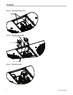
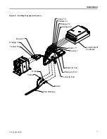
Страница 8: ...CC SVN190B EN Figure 3 Removing the plug screws Remove Screws Figure 4 Mounting the controller Edge Protector Edge Protector Edge Protector Figure 5 Mounted controller I In ns st ta al ll la at ti io on n ...

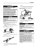
Страница 9: ...d N No ot te e If the high pressure service port is on another Tee refer to Figure 8 p 9 for connection Figure 8 Tee and transducer installed on high pressure service port 4 Tighten flare nut securely to the high pressure service port and check for leaks Wiring N NO OT TI IC CE E W Wi ir re e D Da am ma ag ge e F Fa ai il lu ur re e t to o f fo ol ll lo ow w i in ns st tr ru uc ct ti io on ns s b ...

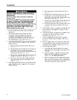
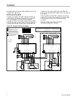
Страница 10: ... in kit harness by making an in line connection Securely attach this in line connection to adjacent wiring with wire ties See Figure 11 p 12 c Connect terminal with black and orange wires to the open tab on SOV1 See Figure 11 p 12 d Connect orange wire with stripped end to Rev valve terminal on low amb controller 1 See Figure 11 p 12 4 FOR HEAT PUMP UNITS ONLY connect Switchover valve 2 SOV2 harne...

Страница 11: ...4 gauge wire harness Yellow T3 Orange T2 Brown T1 Brown to Fan Orange to Fan Yellow to Fan Yellow T3 Yellow L3 Orange T2 Orange L2 Brown T1 Brown L1 Low Ambient Controller Brown Yellow Orange Fan Harness I In ns st ta al ll la at ti io on n ...

Страница 12: ...er valve connections 1 Switch Over Valve SOV 1 Black Blue Switch Over Valve SOV2 Figure 11 Switch over connections Black Blue Orange Switch Over Valve SOV1 Switch Over Valve SOV2 Orange Orange Rev Valve I In ns st ta al ll la at ti io on n ...

Страница 13: ...ACC SVN190B EN 13 Figure 12 Jumper harness Low Ambient Controller Red Wire Black Wire Figure 13 Installing 24VAC harness Low Ambient Controller Red Wire Black Wire I In ns st ta al ll la at ti io on n ...

Страница 14: ...14 ACC SVN190B EN Figure 14 Transducer wires Low Ambient Controller Transducer Transducer Low Ambient Controller Black Red Blue White or Green I In ns st ta al ll la at ti io on n ...

Страница 15: ...MP N O T AMBIENT P1 P2 RED P2 B W G P1 B W G Y1 Y2 T STAT 24 VAC COMMON Y2 N O Jumper Position for TWA Models Heat Pump For heat pump applications the heat pump select jumper must be in the N C position see Figure 17 p 15 Figure 17 Jumper position for TWA N C C Y1 REV VALVE P1 P2 BLK HEAT PUMP N O T AMBIENT P1 P2 RED P2 B W G P1 B W G Y1 Y2 T STAT 24 VAC COMMON Y2 N C Operation The low ambient con...

Страница 16: ...OF CONDUCTORS FAILURE TO DO SO MAY CAUSE DAMAGE TO THE EQUIPMENT CAUTION UTILICE ÚNICAMENTE CONDUCTORES DE COBRE LAS TERMINALES DE LA UNIDAD NO ESTÁN DISEÑADAS PARA ACEPTAR OTROS TIPOS DE CONDUCTORES SI NO LO HACE PUEDE OCASIONAR DAÑO AL EQUIPO N UTILISER QUE DES CONDUCTEURS EN CUIVRE LES BORNES DE L UNITÉ NE SONT PAS CONÇUES POUR RECEVOIR D AUTRES TYPES DE CONDUCTEURS L UTILISATION DE TOUT AUTRE ...

Страница 17: ... r o ot th he er r i in nd di iv vi id du ua al l w wh ho o h ha as s b be ee en n t tr ra ai in ne ed d i in n h ha an nd dl li in ng g l li iv ve e e el le ec ct tr ri ic ca al l c co om mp po on ne en nt ts s p pe er rf fo or rm m t th he es se e t ta as sk ks s Before leaving the installation observe for correct operation through the desired pressure range see Table 3 p 18 Table 2 Troubleshoot...

Страница 18: ...able 3 Pressure vs voltage Pressure psig Voltage Vdc 0 0 5 50 0 9 100 1 3 150 1 7 200 2 1 250 2 5 300 2 9 350 3 3 400 3 7 450 4 1 500 4 5 O Op pe er ra at ti io on n a an nd d T Tr ro ou ub bl le es sh ho oo ot ti in ng g ...

Страница 19: ...ACC SVN190B EN 19 N No ot te es s ...

Страница 20: ...lease visit trane com or americanstandardair com Trane and American Standard have a policy of continuous product and product data improvement and reserve the right to change design and specifications without notice We are committed to using environmentally conscious print practices ACC SVN190B EN 20 Aug 2021 Supersedes ACC SVN190A EN March 2020 2021 ...

Отзывы: