10
ACC-SVN190B-EN
W
WA
AR
RN
NIIN
NG
G
P
Prro
op
pe
err F
Fiie
elld
d W
Wiirriin
ng
g a
an
nd
d G
Grro
ou
un
nd
diin
ng
g
R
Re
eq
qu
uiirre
ed
d!!
F
Fa
aiillu
urre
e tto
o ffo
ollllo
ow
w cco
od
de
e cco
ou
ulld
d rre
essu
ulltt iin
n d
de
ea
atth
h o
orr
sse
erriio
ou
uss iin
njju
urry
y..
A
Allll ffiie
elld
d w
wiirriin
ng
g M
MU
US
ST
T b
be
e p
pe
errffo
orrm
me
ed
d b
by
y q
qu
ua
alliiffiie
ed
d
p
pe
errsso
on
nn
ne
ell.. IIm
mp
prro
op
pe
errlly
y iin
nsstta
alllle
ed
d a
an
nd
d g
grro
ou
un
nd
de
ed
d
ffiie
elld
d w
wiirriin
ng
g p
po
osse
ess F
FIIR
RE
E a
an
nd
d E
EL
LE
EC
CT
TR
RO
OC
CU
UT
TIIO
ON
N
h
ha
azza
arrd
dss.. T
To
o a
av
vo
oiid
d tth
he
esse
e h
ha
azza
arrd
dss,, y
yo
ou
u M
MU
US
ST
T ffo
ollllo
ow
w
rre
eq
qu
uiirre
em
me
en
nttss ffo
orr ffiie
elld
d w
wiirriin
ng
g iin
nsstta
alllla
attiio
on
n a
an
nd
d
g
grro
ou
un
nd
diin
ng
g a
ass d
de
essccrriib
be
ed
d iin
n N
NE
EC
C a
an
nd
d y
yo
ou
urr llo
occa
all//
sstta
atte
e//n
na
attiio
on
na
all e
elle
eccttrriicca
all cco
od
de
ess..
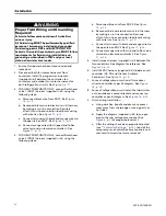
1. Ensure Unit power has been disconnected and
locked out.
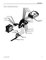
2. Disconnect both fan motor harnesses from
contactors, install 14 gauge wire harnesses
(supplied in kit) between the controller, fan
contactors and outdoor fan motor harnesses for
both refrigeration circuits. See
3. FOR HEAT PUMP UNITS ONLY, connect Switchover
valve 1 (SOV1) harness (supplied in kit) using the
following steps:
a. Disconnect black wire from SOV1. See
.
b. Reconnect black wire to black wire in kit harness
by making an in-line connection. Securely
attach this in-line connection to adjacent wiring
with wire ties. See
c. Connect terminal with black and orange wires to
the open tab on SOV1. See
.
d. Connect orange wire with stripped end to Rev
valve terminal on low amb controller 1. See
4. FOR HEAT PUMP UNITS ONLY, connect Switchover
valve 2 (SOV2) harness (supplied in kit) using the
following steps:
a. Disconnect blue wire from SOV2. See
.
b. Reconnect blue wire to black wire in kit harness
by making an in-line connection. Securely
attach this in-line connection to adjacent wiring
with wire ties. See
c. Connect terminal with black and orange wires to
the open tab on SOV2. See
.
d. Connect orange wire with strip end to Rev valve
terminal on low amb controller 2. See
.
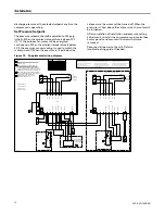
5. Install jumper harness (supplied in kit) between the
two controllers. See diagram for reference. See
.
6. Install 24VAC harness (supplied in kit) between unit
controller (UC-P5) and the Low Ambient
Controller1. See
7. For each refrigeration circuit install transducer
wires to controller as per kit diagram. See
8. For each refrigeration circuit install the thermistors
on the outdoor air sensor bracket and connect on
controller as per kit diagram. See
9. Finish wiring installation.
a. Using wire ties, bundle and dress any excess
wires away from sharp edges, moving parts, or
hot tubes.
b. Apply the diagram (supplied in kit) to an open
area on the low voltage access panel. See
for proper replacement.
c. After the settings have been properly adjusted
(see “
), reinstall the
compressor and control box access panels and
secure with screws that were removed.
Содержание Odyssey BAYLOAMS20
Страница 19: ...ACC SVN190B EN 19 N No ot te es s ...


