IFM O2D93 Series, Руководство по эксплуатации
На сайте manualshive.com вы можете бесплатно скачать инструкции по эксплуатации для продукта IFM O2D93 Series. Эti "Operating Instructions Manual" помогут вам максимально эффективно использовать ваше устройство. Не забудьте скачать их прямо сейчас!
Поделиться
Скачать


Отзывы:
Нет отзывов
Похожие инструкции для O2D93 Series
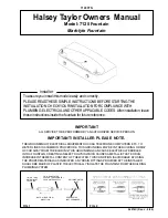
7120
Бренд: Halsey Taylor Страницы: 4

1654830
Бренд: MD SPORTS Страницы: 15

Blackpool Bank 69267
Бренд: deVRIES Страницы: 8

232236U
Бренд: SLV Страницы: 5

L-PS803PST-A
Бренд: Garden Treasures Страницы: 18

NTE2541D
Бренд: Tricam Страницы: 12

721.0733.000
Бренд: HAMPTON BAY Страницы: 28

Fast Framer
Бренд: G&T SALES Страницы: 2

272-2191
Бренд: Backyard Creations Страницы: 2

nettuno F4.177.03
Бренд: Viabizzuno Страницы: 12

KIS12994
Бренд: Gardiun Страницы: 26

FBCICONT-S
Бренд: CobraCo Страницы: 4

Beauvais FT-167
Бренд: Campania International Страницы: 4

GT-507-U
Бренд: GT-Lite Страницы: 2

BAULE EVO 80 BAULE EVO 120
Бренд: garofalo Страницы: 16

Lederam F2
Бренд: Catellani & Smith Страницы: 4

SPS 250/6
Бренд: T.I.P. Страницы: 88

GDL2
Бренд: Knightsbridge Страницы: 7


