mobileIoT gateway
CR3150
9
4.5 Accelerometers and gyro sensors
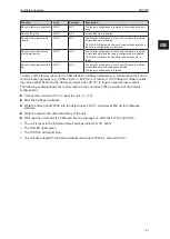
The accelerometers measure acceleration along the X, Y and Z axes. The 3-axis gyro sensor
determines the angular velocity on the X, Y and Z axes. This data is evaluated and can be forwarded
to the controller via CAN bus.
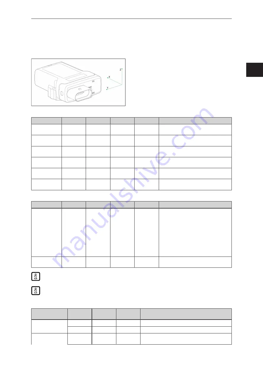
The data of the acceleration/gyro sensors is accessed via the following objects:
Object
Index
Subindex
Type
Default
Description
Acceleration – X-
axis
0x544D
0x00
R32
ro
—
Current acceleration X-axis (unit: g)
Acceleration – Y-
axis
0x544D
0x01
R32
ro
—
Current acceleration Y-axis (unit: g)
Acceleration – Z-
axis
0x544D
0x02
R32
ro
—
Current acceleration Z-axis (unit: g)
Gyroscope – X-
axis
0x544D
0x03
R32
ro
—
Current acceleration X-axis (unit: °/second)
Gyroscope – Y-
axis
0x544D
0x04
R32
ro
—
Current acceleration Y-axis (unit: °/second)
Gyroscope – Z-
axis
0x544D
0x05
R32
ro
—
Current acceleration Z-axis (unit: °/second)
The unit can send this data via the CAN interface. The configuration is made via the following objects:
Object
Index
Subindex
Type
Default
Description
DeviceMode
0x4001
0x02
U8
rw
—
Bit 0: compatibility mode with unit CR3114
(1 s cycle)
Bit 1: forward device status via CAN bus (1 s
cycle)
Bit 2: forward complete GNSS data via CAN
bus (1 s cycle)
Bit 3: forward input/output data via CAN bus
(1 s cycle)
Bit 4: forward acceleration and gyro-
scope data via CAN bus (100 ms cycle)
Movement Ba-
seID
0x4005
0x05
U16
0x500
COB ID start address for acceleration and
gyroscope data transmission (100 ms cycle)
All data available in the respective device mode are sent via the CAN1 interface.
The exact index and subindex can be found in the corresponding EDS file.
The acceleration and gyroscope data are mapped to the following CAN messages:
COB ID
Start byte
Length
(bytes)
Type
Object
Movement
0x00
0
4
R32
Acceleration – X-axis
4
4
R32
Acceleration – Y-axis
Movement
0x01
0
4
R32
Acceleration – Z-axis
GB


