


PRS-300 Series
OPERATION
11
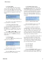
3.4.8 STO, RCL Keys
The
STO
and
RCL
key are used to store
user de
fi
ned values into memory. Press
STO
key followed by 0 to 9 in the numeric keypad
stores the currently shown resistance value into
that memory location.
Press
RCL
key followed by 0 to 9 in the
numeric keypad recalls the resistance value
saved into memory to the currently displayed
value.
3.4.9 VOLT Key
The
VOLT
key should normally be set
to 0.5 V which allows us of the full resistance
range of the PRS-300. Pressing the
VOLT
key
followed by a numeric value representing the
maximum voltage being used in the applica-
ton will limit the lowest resistance that can be
entered to prevent damage to the PRS-300.
The limited is based upon a maximum of
1 W being applied to the resistors. Note that
0.5 W is the maximum recommended and op-
eration at 1 W can cause the internal resistors
to drift beyond speci
fi
cation.
3.4.10 2 and 4 Wire Kelvin Lead Con-
nections
2-wire
or
4-wire
operation can be selected
from by pressing the
MENU
button, selecting
CONFIGURE
, pressing the “2” will change
between 2-wire and 4-wire modes.
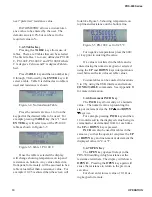
The use of 4W mode with Kelvin leads
minimize the effects of contact resistance and
gives best performance. In 4-wire remove the
shorting links from the high and low terminal
pairs.
Figure 3-6 4-Terminal shorting links not con-
nected
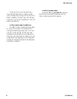
2W mode should be used when connect-
ing to a 2 wire device or if the PRS-300 will be
used as a standard 2-terminal resistor such as
RTD simulation. In 2-wire mode shorting links
must be installed across high and low terminal
pairs.
Figure 3-7 Two terminal with shorting links
3.4.11 Thermal emf Considerations
The PRS Series uses high-quality, low-
emf components. Thermal emf is primarily
attributable to the temperature difference
between the leads of the relay and the contacts
when temperature is applied to the coil. This
emf is of the order of 5
μ
V per relay, but is not
usually additive. The typical worst case is <15
μ
V.
If the effect of tens of microvolts is
signi
fi
cant to your application, connect to the
instrument with low-thermal-emf materials
only. Copper wire and copper alloys are rec-
ommended; brass and steel should be avoided.
Tinned copper and solder are acceptable.
Содержание PRS-300 Series
Страница 2: ...TEL 516 334 5959 800 899 8438 FAX 516 334 5988 www ietlabs com IET LABS INC...
Страница 16: ...SPECIFICATIONS PRS 300 Series 6...
Страница 24: ...PRS 300 Series IEEE INTERFACE OPTION 14...
Страница 34: ...PROGRAMMING PRS 300 Series 24...
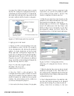
Страница 42: ...PRS 300 Series PRS DMM SOFTWARE 32...
Страница 50: ...PRS 300 Series APPENDIX B 40...