background image

IER 567 Counter Top Printer – Level 1 Maintenance Manual  
N00272A 


Ce document est la propriété de IER et ne doit pas être reproduit ou communiqué sans autorisation écrite 

This document is the property of IER and may not be reproduced or communicated without prior written authorization 

Page 3-14 
Revision level: 1 
October 28, 2003 


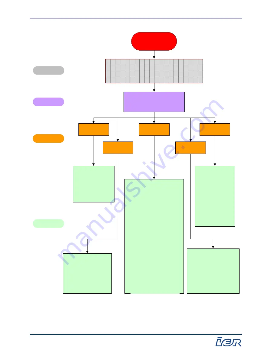
Paper jam in zone E

Paper jam at printhead

Message displayed

Symptoms

Probable causes

Corrective actions

‰

Perform an operational test on
the magnetic and print motors
using the Tests submenu (see
Chapter 2 of this manual).

‰

Check the platen condition.

‰

Check the condition of the drive
assemblies and pressure rollers.

‰

Clean the drive assemblies and
platen.

‰

Perform an operational check on
the clutch solenoid using the
Tests submenu (see Chapter 2
of this manual).

‰

Check that the printhead is
correctly lowered using the
Tests submenu (see Chapter 2
of this manual) .

‰

If the printhead cam is displaced
when lowered, check the
printhead support spring guide
for fouling or replace the printer.

‰

In case of thermal transfer,
check the condition of the
transfer ribbon (see figures pp.
3-22 and 3-25).

‰

Clean the print sensor.

‰

Check that the protective
film tape is in place.

‰

Test the sensor using the
Tests submenu (see
Chapter 2 of this manual).

‰

Replace the printer.

‰

Check that the front
stacker is not full.

‰

Check the stacker
full sensor using
the Tests submenu
(see Chapter 2 of
this manual).

‰

Check that the front
stacker deflector
wire rotates freely.

‰

Replace the printer.

‰

Open the hinged top
part and inspect/
clean the paper path
between the
magnetic sensor
and front stacker.

‰

Replace the printer.

‰

Check the physical
condition of the coupons.

‰

Check that the physical
characteristics of the
coupons conform to IATA
specifications.

‰

Replace the faulty
coupon bin(s).

Drive

Coupons

Paper path

Stacker

Print sensor

C O U P O N

J A M

[

E

]

P l e a s e

c o r r e c t

a n d

t h e n

p r e s s

" E S C "

S N : X X X X X X X


Figure 3-7  Paper jam in zone E – Message displayed: COUPON JAM [E] 

transfer ribbon (see figures pp. 
3-22 et 3-25). 

Содержание 567

Страница 1: ...uthorization Revision Level 2 Nov 28 2005 IER 567 COUNTER TOP PRINTER LEVEL 1 MAINTENANCE MANUAL N00272A IER Siège Headquarters 3 rue Salomon de Rothschild BP320 92156 SURESNES Cedex FRANCE Tel 33 0 1 41 38 60 00 Fax 33 0 1 41 38 62 00 Telex 620289 Web www ier fr Service Clients Customer Service Fax 33 0 1 41 38 62 72 Translated from French Manuel de Maintenance Niveau 1 Imprimante IER 567 Modèle ...

Страница 2: ...without prior written authorization LIST OF PAGES i ii iii iv v vi 1 1 1 2 Blank 1 3 1 4 Blank 1 5 1 6 1 7 1 8 1 9 1 10 Blank 2 1 2 2 Blank 2 3 2 4 Blank 2 5 2 6 Blank 2 7 2 8 2 9 2 10 2 11 2 12 2 13 2 14 Blank 2 15 2 16 2 17 2 18 Blank 2 19 2 20 Blank 2 21 2 22 Blank 2 23 2 24 Blank 2 25 2 26 Blank 2 27 2 28 2 29 2 30 Blank 2 31 2 32 Blank 3 1 3 2 3 3 3 4 Blank 3 5 3 6 3 7 3 8 3 9 3 10 3 11 3 12 ...

Страница 3: ...11 UETZE Phone 49 0 5173 6906 30 Fax 49 0 5173 6906 50 UNITED KINGDOM IER Ltd Unit G4 Middlesex Business Centre Bridge Road SOUTHALL MIDDX UB2 4AB Phone 44 0 208 744 7650 Fax 44 0 208 744 7670 JAPAN IER Tokyo Yoshitoku Bldg 8F 3 15 14 Shiba Minato ku TOKYO 105 0014 Phone 81 3 5730 9001 Fax 81 3 5730 9002 SINGAPORE IER Pte LTd 298 Tiong Bahru Road 09 01 03 Central Plaza SINGAPORE 168730 Phone 65 62...

Страница 4: ... radio frequency energy and if not installed and used in accordance with the instruction manual may cause harmful interference to radio communications Operation of this equipment in a residential area is likely to cause harmful interference in which case the user will be required to correct the interference at his own expense Use of a shielded cable is required to comply within Class A limits of P...

Страница 5: ...nt est la propriété de IER et ne doit pas être reproduit ou communiqué sans autorisation écrite This document is the property of IER and may not be reproduced or communicated without prior written authorization MODIFICATIONS Revision Level Date Modifications 1 Oct 28 2003 2 Nov 28 2005 Chapter 1 and Chapter 2 ...

Страница 6: ...7 Printer It includes the following chapters Chapter 1 Preventive Maintenance This chapter defines The operations to be performed The frequency of these operations The rules to be applied Tools and servicing products For level 1 preventive maintenance Chapter 2 Maintenance Sheets This chapter consists of sheets giving the procedures for performing the following operations Dusting Cleaning Removal ...

Страница 7: ...8 2005 Ce document est la propriété de IER et ne doit pas être reproduit ou communiqué sans autorisation écrite This document is the property of IER and may not be reproduced or communicated without prior written authorization CHAPTER1 LEVEL 1 PREVENTIVE MAINTENANCE Revision Level 2 Nov 28 2005 ...

Страница 8: ...72A Page 1 2 Revision Level 2 Nov 28 2005 Ce document est la propriété de IER et ne doit pas être reproduit ou communiqué sans autorisation écrite This document is the property of IER and may not be reproduced or communicated without prior written authorization ...

Страница 9: ...cated without prior written authorization TABLE OF CONTENTS Title Page LEVEL 1 PREVENTIVE MAINTENANCE 1 5 1 1 General 1 5 1 2 Level 1 Maintenance Schedule 1 5 1 3 Part Replacements Authorized at Level 1 Maintenance 1 5 1 4 Test Coupons 1 6 1 4 1 Statistics Coupon 1 6 1 4 2 Configuration Coupon 1 6 1 4 3 Status Coupon 1 7 1 4 4 Network Information Coupon 1 8 1 5 General Block Diagram of Interconnec...

Страница 10: ...72A Page 1 4 Revision Level 2 Nov 28 2005 Ce document est la propriété de IER et ne doit pas être reproduit ou communiqué sans autorisation écrite This document is the property of IER and may not be reproduced or communicated without prior written authorization ...

Страница 11: ... A 2 This coupon shows the error counters which can be analyzed to focus maintenance on problem areas The printer is set on a tabletop for level 1 preventive maintenance Personnel Frequency Estimated time Maintenance technician Once a year for an average of 300 coupons printed per day Every 6 months for an average of 600 coupons printed per day 30 minutes Type of operations Cleaning agents Procedu...

Страница 12: ...s Zone B 1234567 1234567 Power on 1234567h Boot revision 0 00 Jams Zone C 1234567 1234567 Remaining ribbon diameter mm Jams Zone D 1235567 1234567 SENSOR BRIGHTNESS THRESHOLD Jams Zone E 1234567 1234567 Magnetic 23 23 Jams Zone S 1234567 1234567 Print 23 23 Cutter Jams 1234567 1234567 Front lgth 23 23 Head Jams 1234567 1234567 Front edge 23 Ribbon Jams 1234567 1234567 Rear edge 23 1 4 2 Configurat...

Страница 13: ...M1 do not appear for network and USB connections 567 STATUS COUPON Serial number 123467 Software main board rev 80450 0 00 Software check sum 0x12345678 ATB specifications AEA1999 Coupon count 1234567 Power on time 1234567 hours Display language French Top print position in tenth of mm 123 Left print position in tenth of mm 123 Thermal mode Thermal paper Ribbon passes 5 Default bin 1 Connexion typ...

Страница 14: ...if the ribbon controller is present The lines concerning Escrow appear only if the escrow bin is present NETWORK INFORMATION Serial Number 1234567 567 IER PIC software revision NIF software revision NIF serial number Program Date 00 00 0000 Ethernet address 12 34 6 78 9A BC Chksum Ox12345678 Keyboard ctrl 80437 0 00 IP address 123 123 12 1 Escrow ctrl 80464 0 00 Subnet mask 123 123 12 1 Ribbon ctr...

Страница 15: ...rial port RS232 auxiliary serial port Ethernet interface PCB Power supply AC power input On Off switch AC power filter Thermal printhead Coupon feeding mechanism Front panel sensor Keypad PCB Display unit Burster raised sensor Ribbon switch Length sensor Front edge sensor Output stacker sensor Front feed sensor escrow version Reject bin sensor Front feed solenoid Magnetic motor Reject bin solenoid...

Страница 16: ...2A Page 1 10 Revision Level 2 Nov 28 2005 Ce document est la propriété de IER et ne doit pas être reproduit ou communiqué sans autorisation écrite This document is the property of IER and may not be reproduced or communicated without prior written authorization ...

Страница 17: ... 28 2005 Ce document est la propriété de IER et ne doit pas être reproduit ou communiqué sans autorisation écrite This document is the property of IER and may not be reproduced or communicated without prior written authorization CHAPTER 2 LEVEL 1 MAINTENANCE SHEETS Revision Level 2 Nov 28 2005 ...

Страница 18: ...72A Page 2 2 Revision Level 2 Nov 28 2005 Ce document est la propriété de IER et ne doit pas être reproduit ou communiqué sans autorisation écrite This document is the property of IER and may not be reproduced or communicated without prior written authorization ...

Страница 19: ...thout prior written authorization TABLE OF CONTENTS Sheet Title Page A TOOLS AND TEST SOFTWARE 2 5 A 1 List of Standard and Specific Tools Consumable Supplies 2 5 A 2 Test Software 2 7 B PROCEDURES 2 15 B 1 General Dusting 2 15 B 2 Cleaning the Printhead Platen and Spring Guide 2 19 B 3 Cleaning the Magnetic Head 2 21 B 4 Cleaning the Trailing Edge Sensor 2 23 B 5 Restoring to Initial Condition 2 ...

Страница 20: ...72A Page 2 4 Revision Level 2 Nov 28 2005 Ce document est la propriété de IER et ne doit pas être reproduit ou communiqué sans autorisation écrite This document is the property of IER and may not be reproduced or communicated without prior written authorization ...

Страница 21: ...qué sans autorisation écrite This document is the property of IER and may not be reproduced or communicated without prior written authorization A TOOLS AND TEST SOFTWARE A 1 List of Standard and Specific Tools Consumable Supplies 1 Standard Tools Cleaning brush Size 10 Torx head screwdriver 2 Cleaning Agents IER standard cleaning kit IER Part S32129A SHEET A 1 IER 567 PRINTER ...

Страница 22: ...72A Page 2 6 Revision Level 2 Nov 28 2005 Ce document est la propriété de IER et ne doit pas être reproduit ou communiqué sans autorisation écrite This document is the property of IER and may not be reproduced or communicated without prior written authorization ...

Страница 23: ...ine power and turn it on The following message is displayed 5 6 7 R E A D Y R e v i s i o n 1 0 0 S N X X X X X X X Where the x s are the printer serial number b Press the On Off line Menu key on the keypad to access the main menu menu scrolling mode The following message is displayed M a i n m e n u Æ P r i n t s t a t u s c o u p o n P r i n t A T B c o u p o n G e n e r a l p a r a m e t e r s ...

Страница 24: ...wo arrow keys M a i n m e n u P r i n t s t a t u s c o u p o n P r i n t A T B c o u p o n Æ G e n e r a l p a r a m e t e r s b Hit Enter to confirm The following message is displayed G e n e r a l P a r a m e t e r s E n t e r p a s s w o r d 0 0 0 0 0 c Enter your password using the arrow keys to select a digit and to change a digit d Hit Enter to confirm The following message is displayed G e...

Страница 25: ...o r y s e t t i n g s Æ C o u n t e r s b Hit Enter to confirm The following message is displayed C o u n t e r s E n t e r p a s s w o r d 0 0 0 0 0 c Enter your password using the arrow keys to select a digit and to change a digit d Hit Enter to confirm The following message is displayed C o u n t e r s Æ P r i n t s t a t i s t i c s M a i n C o u n t e r s P a r t i a l C o u n t e r s e Hit E...

Страница 26: ... is displayed C o m m u n i c a t i o n E n t e r p a s s w o r d 0 0 0 0 0 c Enter your password using the arrow keys and The following message is displayed C o m m u n i c a t i o n Æ N e t w o r k s e t t i n g s R s 2 3 2 C O M 1 S e t t i n g s H o s t p r o t o c o l d Hit Enter to confirm The following message is displayed N e t w o r k s e t t i n g s Æ P r i n t n e t w o r k c p n I P A ...

Страница 27: ...C o u n t e r s Æ T e s t s b Hit Enter to confirm The following message is displayed T e s t s E n t e r p a s s w o r d 0 0 0 0 0 c Enter your password using the arrow keys d Hit Enter to confirm The following message is displayed T e s t s Æ P r i n t A T B c o u p o n F o n t t e s t c o u p o n R a m d i s k l i s t i n g e Scroll through the items using the arrow keys to select an item refer...

Страница 28: ... i n 3 s w i t c h o n NOTE The switch name and state remain displayed until you actuate another switch The name of the last switch actuated and its state remain displayed until you exit from this menu 9 Testing the Motors a Select the Test monitor item using the two arrow keys T e s t s T e s t d e t e c t o r s Æ T e s t m o n i t o r H e a d t e m p e r a t u r e b Hit Enter to confirm The foll...

Страница 29: ...the Head temperature item using the two arrow keys T e s t s T e s t m o n i t o r Æ H e a d t e m p e r a t u r e B a d h e a d d o t s b Hit Enter to confirm The following message is displayed H e a d t e m p e r a t u r e x x x o C where XXX is the temperature in C c Hit Esc to stop the test 11 Testing the Number of Failed Printhead Heating Elements a Select the Bad head dots item using the two...

Страница 30: ...2A Page 2 14 Revision Level 2 Nov 28 2005 Ce document est la propriété de IER et ne doit pas être reproduit ou communiqué sans autorisation écrite This document is the property of IER and may not be reproduced or communicated without prior written authorization ...

Страница 31: ... screwdriver 2 Cleaning Agents Refer to Sheet A 1 3 Related Maintenance Sheets Sheet A 1 Sheet B 3 and Sheet B 5 4 Procedure IMPORTANT The printer must be disconnected from AC line power and host computer before beginning this procedure a Open the operator access door 1 and unlock the electronics module 3 using the size 10 Torx head screwdriver 2 b Remove the ribbon cartridge if the printer is of ...

Страница 32: ...t pas être reproduit ou communiqué sans autorisation écrite This document is the property of IER and may not be reproduced or communicated without prior written authorization e Close the operator access door 1 f Press down the cover retainer direction of arrow A 6 and rotate the electronics module 3 very carefully in the direction of arrow B 3 6 1 ...

Страница 33: ...Hold the magnetic module 9 in the raised position see Sheet B 3 k Use the air duster from the IER cleaning kit IER P N S32129A to remove dust from the entire paper path Pay particular attention to the area around the burster 10 l Using a vacuum cleaner adapted to printer cleaning remove the dust from the electronics module 3 module and central mounting plate m Return the magnetic module 9 to its i...

Страница 34: ...2A Page 2 18 Revision Level 2 Nov 28 2005 Ce document est la propriété de IER et ne doit pas être reproduit ou communiqué sans autorisation écrite This document is the property of IER and may not be reproduced or communicated without prior written authorization ...

Страница 35: ...t computer before beginning this procedure a Open the operator access door and raise the thermal printhead module see Sheet C 1 b Clean the printhead with a cleaner tube 1 from the IER cleaning kit IER Part S32129A c Clean the entire surface of platen 2 with a damp cloth moistened with cleaning agent from the cleaning kit d Return the thermal printhead module to its initial position see Sheet C 1 ...

Страница 36: ...2A Page 2 20 Revision Level 2 Nov 28 2005 Ce document est la propriété de IER et ne doit pas être reproduit ou communiqué sans autorisation écrite This document is the property of IER and may not be reproduced or communicated without prior written authorization ...

Страница 37: ...IER Part S32129A 3 Procedure IMPORTANT The printer must be disconnected from AC line power and host computer before beginning this procedure a Open the operator access door b Grip the locking tab 1 and tilt up the magnetic module 2 c Hold the magnetic module 2 in raised position d Clean the entire surface of the magnetic head 3 with a cleaning kit swab moistened with cleaning agent also from the c...

Страница 38: ...2A Page 2 22 Revision Level 2 Nov 28 2005 Ce document est la propriété de IER et ne doit pas être reproduit ou communiqué sans autorisation écrite This document is the property of IER and may not be reproduced or communicated without prior written authorization ...

Страница 39: ... computer before beginning this procedure a Open the operator access door b Loosen the trailing edge sensor 2 mounting screw 1 c Remove the sensor 2 from its support without disconnecting it d Remove the two protective sensor covers 3 from their respective seats and clean them with compressed air form the dust remover can and if necessary with a swab from the cleaning kit slightly dampened with cl...

Страница 40: ...2A Page 2 24 Revision Level 2 Nov 28 2005 Ce document est la propriété de IER et ne doit pas être reproduit ou communiqué sans autorisation écrite This document is the property of IER and may not be reproduced or communicated without prior written authorization ...

Страница 41: ...k that the magnetic module 1 is correctly snapped in its housing b Check that the hinged top part 2 is correctly locked in lowered position c Check that the rotating flange 3 is correctly positioned on the central mounting plate d Check that the printhead 4 is snapped on the front and in place in its support see Sheet C 1 e Reconnect the printer to the host computer and AC line power f Install the...

Страница 42: ...2A Page 2 26 Revision Level 2 Nov 28 2005 Ce document est la propriété de IER et ne doit pas être reproduit ou communiqué sans autorisation écrite This document is the property of IER and may not be reproduced or communicated without prior written authorization ...

Страница 43: ... Thermal Printhead Module Estimated Time 5 min 1 Tools Required None 2 Removal IMPORTANT The printer must be disconnected from AC line power and host computer before beginning this procedure a Open the operator door and place the rotating flange in raised position phase 1 phase 2 and phase 3 b Hold onto the rotating flange during phase 3 and do not release it until it is in place against the centr...

Страница 44: ...te This document is the property of IER and may not be reproduced or communicated without prior written authorization d Push the thermal printhead module 2 back in the direction of arrow A up to the rear stop in the direction of arrow B e Then tilt the thermal printhead module 2 upwards in the direction of arrow C f Then remove it from its support 3 in the direction of arrow D and set it aside 2 2...

Страница 45: ...ead module with the two pins 4 opposite the two holes 5 in the support b Fit the two pins all the way into their housings in the direction of the two arrows E c Tilt the thermal printhead module forward in its support in the direction of arrow F d Push the thermal printhead module forward in the direction of the two arrows G until it snaps into place the two clicks should be heard e Reconnect the ...

Страница 46: ...2A Page 2 30 Revision Level 2 Nov 28 2005 Ce document est la propriété de IER et ne doit pas être reproduit ou communiqué sans autorisation écrite This document is the property of IER and may not be reproduced or communicated without prior written authorization ...

Страница 47: ...nter must be disconnected from AC line power and host computer before beginning this procedure a Raise the small tab 1 and remove the actuator lever 2 from the printhead support 3 3 Installation a Position the actuator lever 2 in front of the printhead support 3 and fit the two actuator lever slots 4 onto the corresponding ridges 5 on the printhead support b Push in the actuator lever until it sna...

Страница 48: ...2A Page 2 32 Revision Level 2 Nov 28 2005 Ce document est la propriété de IER et ne doit pas être reproduit ou communiqué sans autorisation écrite This document is the property of IER and may not be reproduced or communicated without prior written authorization ...

Страница 49: ...tober 28 2003 Ce document est la propriété de IER et ne doit pas être reproduit ou communiqué sans autorisation écrite This document is the property of IER and may not be reproduced or communicated without prior written authorization CHAPTER 3 TROUBLESHOOTING Revision level 1 October 28 2003 ...

Страница 50: ...ment is the property of IER and may not be reproduced or communicated without prior written authorization Page 3 2 Revision level 1 October 28 2003 TABLE OF CONTENTS Title Page TROUBLESHOOTING 3 5 3 1 Introduction 3 5 3 1 1 Test Keypad 3 5 3 1 2 Printer LEDs 3 5 3 1 3 Failures during Operation 3 5 3 2 General Organization 3 6 3 2 1 General 3 6 3 2 2 Troubleshooting Method 3 6 ...

Страница 51: ...MAG ENCODE ERROR 123 123 123 3 15 Figure 3 9 Magnetic problem Message displayed WARNING MAG READING ERROR 123 123 123 3 16 Figure 3 10 Rear paper feed problem Message displayed No message displayed 3 17 Figure 3 11 Front feed problem Message displayed No message displayed 3 18 Figure 3 12 Burster problem burster blade stuck in cutting zone Message displayed CUTTER JAM 3 19 Figure 3 13 Printhead po...

Страница 52: ...A Ce document est la propriété de IER et ne doit pas être reproduit ou communiqué sans autorisation écrite This document is the property of IER and may not be reproduced or communicated without prior written authorization Page 3 4 Revision level 1 October 28 2003 ...

Страница 53: ...1 maintenance It describes a range of failures that may occur during operation but does not claim to be exhaustive IER 567 printer maintenance is faciltated by use of the test keypad and observation of the two LEDs inside the printer 3 1 1 Test Keypad The test keypad is used to configure and perform maintenance run maintenance tests of IER 567 printers when the printer keypad is unavailable The te...

Страница 54: ...ject bin Such failures mainly concern Paper feed bins rear feeders straight and curved paper path front stacker reject bin front feeder Magnetic processing encoding and reading Thermal printing Read of the stock control number SCN option 3 2 2 Troubleshooting Method After identification of the cause of a failure and the items involved each item is checked in three stages Physical check drive wear ...

Страница 55: ...be reproduced or communicated without prior written authorization The terms top and bottom refer to a printer set on its baseplate The printer is repaired by Cleaning any soiled components refer to Chapter 2 of this manual Standard replacement of any defective components refer to Chapter 2 of this manual Adjustment of the failed component or functional system refer to Chapter 2 of this manual For ...

Страница 56: ...eder 2 actuator lever solenoid using the Tests submenu see Chapter 2 of this manual Check the condition of the drive assemblies and pressure rollers Clean the drive assemblies Replace the printer Test the magnetic sensor using the Tests submenu see Chapter 2 of this manual Check that nothing blocks the magnetic sensor Clean the sensor Replace the printer Check the physical condition of the coupons...

Страница 57: ...sensors Test the sensors using the Tests submenu see Chapter 2 of this manual Replace the printer Check the physical condition of the coupons Check that the coupons can move freely especially in their boxes Check that the physical characteristics of the coupons conform to IATA specifications Replace the faulty coupon bin Check that the hinged top part is closed Open the hinged top part and if nece...

Страница 58: ...drive assemblies Replace the printer Check the physical condition of the coupons Check that the physical characteristics of the coupons conform to IATA specifications Replace the faulty coupon bin s Paper path Check that the hinged top part is closed Open the hinged top part and inspect clean the paper path Check that the rear feed routing system is free and moves up correctly Open the rotating fl...

Страница 59: ... operational check on the clutch solenoid using the Tests submenu see Chapter 2 of this manual Replace the printer Check the physical condition of the coupons Check that the coupons can move freely especially in their boxes Check that the physical characteristics of the coupons conform to IATA specifications Replace the faulty coupon bin s Check that the rotating flange is closed Open the rotating...

Страница 60: ... two sensors Test the sensors using the Tests submenu see Chapter 2 of this manual Replace the printer Check the physical condition of the coupons Check that the coupons can move freely especially in their boxes Check that the physical characteristics of the coupons conform to IATA specifications Replace the faulty coupon bin Check that the hinged top part is closed Open the hinged top part and in...

Страница 61: ...c motor using the Tests submenu see Chapter 2 of this manual Replace the printer Clean the two sensors Test the sensors using the Tests submenu see Chapter 2 of this manual Replace the printer Check the physical condition of the coupons Check that the physical characteristics of the coupons conform to IATA specifications Replace the faulty coupon bin s Make sure the burster blade is raised If this...

Страница 62: ...am is displaced when lowered check the printhead support spring guide for fouling or replace the printer In case of thermal transfer check the condition of the transfer ribbon see figures pp 3 22 and 3 25 Clean the print sensor Check that the protective film tape is in place Test the sensor using the Tests submenu see Chapter 2 of this manual Replace the printer Check that the front stacker is not...

Страница 63: ... the coupons have a magnetic stripe Check the coupon feed direction Check the physical condition of the coupons Check that the physical characteristics of the coupons conform to IATA specifications Replace the faulty coupon bin s Paper path Check that the hinged top part and rotating flange are closed Open the hinged top part and rotating flange and inspect clean the paper path Replace the printer...

Страница 64: ... this manual Clean the sensor Replace the printer Check that the coupon has a magnetic stripe Check the physical condition of the coupons Check that the physical characteristics of the coupons conform to IATA specifications Replace the faulty coupon bin s Magnetic problem Paper path Check that the hinged top part and rotating flange are closed Open the hinged top part and rotating flange and inspe...

Страница 65: ...ng the Tests submenu see Chapter 2 of this manual Perform an operational test on the feeder 1 feeder 2 actuator lever solenoid using the Tests submenu see Chapter 2 of this manual Replace the printer Test the feed sensor s using the Tests submenu see Chapter 2 of this manual Check that the sensor s is are retained by the central mounting plate retaining pins not broken Replace the printer Rear pap...

Страница 66: ...ctive actions Drive not operational Front paper feed problem NO MESSAGE DISPLAYED Drive Paper presence detection Perform an operational test on the magnetic motor using the Tests submenu see Chapter 2 of this manual Replace the printer Test the front feed sensor using the Tests submenu see Chapter 2 of this manual Check the condition of the sensor support Replace the printer Drive operational Fron...

Страница 67: ...eck the physical condition of the coupons Check that the physical characteristics of the coupons conform to IATA specifications especially cutting forces and dimensions Replace the faulty coupon bin s Paper path Check that the hinged top part is closed Open the hinged top part and if necessary the rotating flange and inspect clean the paper path Replace the printer Check that the hinged top part a...

Страница 68: ... position Printhead raising control Printhead raised lowered sensors Perform an operational test on the cam motor using the Tests submenu see Chapter 2 of this manual Check for hard spots Clean the spring loaded disk and the cylindrical cam Replace the printer Test the sensors using the Tests submenu see Chapter 2 of this manual Replace the printer Message displayed Symptoms Probable causes Correc...

Страница 69: ...ly on the central mounting plate side Check that the printhead is correctly lowered using the Tests submenu see Chapter 2 of this manual If the printhead cam is displaced when lowered check the printhead support spring guide for fouling Replace the thermal printhead Replace the printer In case of thermal transfer if the ribbon is wrinkled feed the ribbon by hand and tauten it before reinstalling t...

Страница 70: ...thermal printhead connections Check that the thermal printhead is snapped in place especially on the central mounting plate side Check that the printhead is correctly lowered using the Tests submenu see Chapter 2 of this manual If the printhead cam is displaced when lowered check the printhead support spring guide for fouling Replace the thermal printhead Replace the printer If the printer is in t...

Страница 71: ...oduced or communicated without prior written authorization Coupon stopped under printhead printing stopped Out of ribbon Install a new ink ribbon Thermal transfer ribbon problem Message displayed Symptoms Probable causes Corrective actions O U T O F R I B B O N P l e a s e c h a n g e r i b b o n c a r t r i d g e a n d t h e n p r e s s E S C Figure 3 16 Thermal transfer ribbon problem coupon sto...

Страница 72: ...ndition Clean the drive assemblies and platen Clean the thermal printhead Check that the printhead is correctly lowered using the Tests submenu see Chapter 2 of this manual If the printhead cam is displaced when lowered or offcentered check the printhead support spring guide for fouling Replace the printer Open the rotating flange and inspect clean the paper path between the magnetic sensor and fr...

Страница 73: ... of IER and may not be reproduced or communicated without prior written authorization Message displayed Symptoms Probable causes Corrective actions Thermal transfer problem Thermal transfer module inoperative Ribbon controller failure Replace the printer H A R D W A R E E R R O R c o n n e c t i o n S N X X X X X X X B a d r b b o n c o n t r o l i Figure 3 18 Thermal transfer problem ribbon contr...

Страница 74: ... state Symptoms Probable causes Printer control Corrective actions Clean the printhead Check the printhead connection Decrease the contrast see Manual N00212A Chapter 2 Bin parameters submenu Replace the printhead Replace the printer Printhead overheating Power supply Replace the printer Environment Check that the external environment conforms to IER temperature and relative humidity specification...

Страница 75: ... and may not be reproduced or communicated without prior written authorization Message displayed Printer power supply switched to fault state Symptoms Probable causes Voltage VTh not cut off when testing the heating elements Corrective actions Replace the printer Power supply problem H A R D W A R E E R R O R P o w e r s u p p l y o u t o f o r d e r S N X X X X X X X Figure 3 20 Power supply prob...

Страница 76: ... Ce document est la propriété de IER et ne doit pas être reproduit ou communiqué sans autorisation écrite This document is the property of IER and may not be reproduced or communicated without prior written authorization Page 3 28 Revision level 1 October 28 2003 ...

Отзывы: