background image

20

3) 

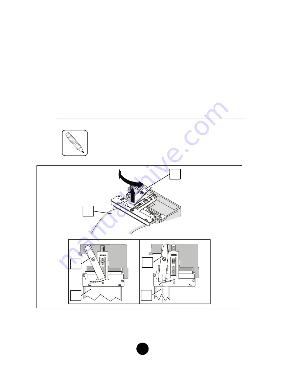
Adjusting the Position of the Printhead Presser

For optimum print contrast the printhead pressure needs to be
adjusted in accordance with the width of the media used.

a) 

Insert some media (2) into the printer and feed it beyond the
printhead.

b) 

Lower the printhead, but do not lock it.

c) 

Grasp the printhead presser at the front (1) and lift it up. Rotate it
so that the center point of its front edge is placed over the center
line (2) of the media (3) in the printer (use the guiding marks on
the printhead support).

NOTE

Should you notice a difference in the print contrast
(left vs. right side of the document), you will have
to take up the adjustment again.

1

1

2

1

3

2

Содержание 540

Страница 1: ...l 3 Dec 3 2002 I I I I I I I I E E E E E E E E R R R R R R R R 5 5 5 5 5 5 5 5 4 4 4 4 4 4 4 4 0 0 0 0 0 0 0 0 P P P P P P P P R R R R R R R R I I I I I I I I N N N N N N N N T T T T T T T T E E E E E E E E R R R R R R R R ...

Страница 2: ...This page is intentionally blank ...

Страница 3: ...to cause harmful interference in which case the user will be required to correct the interference at his own expense Use of a shielded cable is required to comply within Class A limits of Part 15 of FCC Rules Pursuant to Part 15 21 of the FCC Rules any changes or modifications to this equipment not expressly approved by IER may cause harmful interference and void the FCC authorization to operate t...

Страница 4: ... 1 INSTALLING ROLL MEDIA 14 2 INSTALLING FANFOLD STOCK 14 E E ADJUSTING THE PRINTER TO THE MEDIA USED 16 1 ADJUSTING THE PAPER PATH WIDTH 16 2 ADJUSTING THE MEDIA SENSOR 18 3 ADJUSTING THE POSITION OF THE PRINTHEAD PRESSER 20 4 MEDIA LOADING 22 F F CALIBRATING THE MEDIA SENSOR 24 1 GENERAL 24 2 CALIBRATING THE MEDIA SENSOR 24 G G OPERATION 26 1 PRINTING A DOCUMENT 26 2 COMMENTS ON THE CUTTER MODUL...

Страница 5: ...EANING 35 3 CLEANING THE PRINTHEAD AND THE PLATEN 36 4 FINAL CHECK 38 I I OPERATING FAULTS 39 1 PAPER OUT CONDITION 39 2 PAPER JAM 39 3 OTHER OPERATING PROBLEMS 41 J J SUPPLIES AND DOCUMENTATION 42 1 LIST OF SUPPLIES 42 2 IER 540 PRINTER TECHNICAL DOCUMENTATION 42 ...

Страница 6: ...nsitive media Truly universal this printer accepts most of the existing types of continuous thermal media rolls or fanfold stock featuring positioning marks such as the translucent space between labels web holes black marks on the front side or back side of the media etc The IER 540 Printer can be equipped with a cutter which separates the printed documents from the stock To adapt the printer to y...

Страница 7: ...uide 2 present document Bag containing the following AC power supply cord 3 Test documents 4 one of which being the printout of the printer configuration NOTE The IER 540 Printer is shipped without supplies media cleaning kit etc We recommend that you save the packing material at least throughout the warranty period B B 1 4 2 3 ...

Страница 8: ... options Height a 215 mm 8 46 in feet included Depth b 340 mm 13 4 in Width c 260 mm 10 2 in Weight without options supplies packing material 9 5 kg 20 95 lbs Operating temperature 5 C to 40 C 41 F to 104 F Relative humidity 20 to 80 without condensation c a b ...

Страница 9: ...3 Front View Right side door 3 To get access to the printer interior swing the right side door 3 up to the steady position Control panel 1 with one key and three indicators Document ejection slot 2 1 2 3 ...

Страница 10: ... to feed blank media from an external stock Additional slot 2 to install an optional communications interface Standard RS232C data I O connector 3 AC power switch 4 AC line power connector 5 Printer identification plate 6 3 5 4 6 1 2 ...

Страница 11: ... are common to all IER 540 Printers Sliding media sensor 1 Paper guide shaft 2 with adjustable paper guide Printhead on retractable mounting 3 Platen 4 Printhead latch 5 As an option the IER 540 Printer can be equipped with a cutter 6 1 2 3 4 5 6 ...

Страница 12: ...ost data I O connector is readily accessible at the rear of the printer IMPORTANT To connect the printer to the host it is essential to use a shielded cable fitted with metal plated connector hoods The cable shield must be attached to the connector hoods a Make sure the AC power switch is set to the 0 position b Plug the data I O connector into the corresponding connector at the rear of the printe...

Страница 13: ...rst to the printer then to the line power outlet NOTE The printer power supply unit is autoranging and selects automatically the line voltage in use b Power up the printer set the power switch to the I position c Check that the Power indicator on the control panel lights up Power The printer will be operational after the two second initialization sequence during which it is busy and cannot receive...

Страница 14: ...following requirements The roll must be parallel to the printer Viewed from the rear the right edge of the media must be placed 15 mm 0 6 in from the central mounting plate of the printer see Figure opposite 2 Installing Fanfold Stock Place the box containing the fanfold stock at the rear of the printer and perform the following Place the box parallel to the printer Viewed from the rear the right ...

Страница 15: ...15 Parallel Parallel 15 mm 0 6 in 15 mm 0 6 in ...

Страница 16: ...pen the right side door b Proceed as follows to unlock the printhead Actuate latch 2 in the direction shown by the arrow The printhead 1 swings open automatically c To adjust the paper path proceed as follows STEP 1 Slide the adjustable paper guide 4 on shaft 3 towards the outside of the printer Rotate guide 4 up STEP 2 Feed some media 5 into the printer Do not lock the printhead STEP 3 Set the me...

Страница 17: ...17 IMPORTANT Guide 6 must always remain up against the central mounting plate of the printer 3 4 5 STEP 1 STEP 2 STEP 3 6 5 ...

Страница 18: ...In addition to the manual sensor adjustments it is necessary to configure the printer at the software level according to the type of positioning mark used see Technical Manual Media sensor settings depend on the type of positioning mark used 1 Pull on the sensor support until you have access to the configuration DIP switches 1 2 Refer to the Figure below to set the switches 1 according to the type...

Страница 19: ...ocate the pointer 2 on the sensor support 1 showing the exact position of the sensor 2 Move the sensor support and center the pointer 2 and thus the sensor with regard to the positioning mark 4 on the media 3 NOTE If the positioning mark is the translucent space between labels web which can be sensed over the entire width of the media position the sensor roughly in the center of the media Position...

Страница 20: ... the printhead b Lower the printhead but do not lock it c Grasp the printhead presser at the front 1 and lift it up Rotate it so that the center point of its front edge is placed over the center line 2 of the media 3 in the printer use the guiding marks on the printhead support NOTE Should you notice a difference in the print contrast left vs right side of the document you will have to take up the...

Страница 21: ... proceed as follows Rotate the printhead 1 in the direction shown by the arrow Lock the printhead by firmly pressing on the green plastic button 3 Latch 2 must snap back into the locked position e Close the right side door 2 1 3 ...

Страница 22: ...inthead latch 2 in the direction of the arrow The printhead 1 swings open automatically 2 Rotate the adjustable paper guide 3 up see Figure opposite 3 Insert the media 4 from the side under the paper guide shaft 5 into the media sensor 6 under the printhead 1 and into the optional cutter 7 if applicable 4 Make sure the media protrudes from the front ejection slot 5 As soon as you have correctly po...

Страница 23: ... direction shown by the arrow Lock the printhead by vigorously pressing on the green plastic button 8 latch 2 snaps back into the locked position 7 Locking the printhead causes the media to be advanced automatically by the printer Close the right side door 6 4 2 1 8 3 5 7 1 3 ...

Страница 24: ...sity of the black mark are not the same depending on the brand of the media To obtain optimum positioning mark sensing the media sensor needs to be calibrated Therefore whenever loading a new type of media the following procedure needs to be carried out by the operator to ensure correct printer operation 2 Calibrating the Media Sensor STEP 1 Insert some media into the printer see Page 22 but do no...

Страница 25: ...Eject Test key and continue doing so while you lock the printhead see Page 23 This starts the calibration process The media is drawn into the printer The media sensor senses the gap between the positioning marks and determines the print zone of a given document At the end of this process the printer correctly positions the document and cuts it if applicable and is then ready for normal media print...

Страница 26: ...ower switch to the I position Make sure the Power indicator lights up c Send a print command from the host to the printer d Check that the Receive indicator flashes This indicator will go out automatically when document printing is completed e Remove the document from the ejection slot at the front of the printer G G ...

Страница 27: ... of the media Otherwise glue from the labels could adhere to the cutter blade and cause blade jamming Cutting Media Presenting a Line of Perforation between the Individual Labels Make sure cutting takes place after the line of perforation and not on the line see Figure below to avoid jagging of the cutting blade For additional information on the cutting position adjustment refer to the IER 540 Pri...

Страница 28: ...28 3 Key and Indicator Functions ...

Страница 29: ...uses the media to be advanced to the next print zone Pressing this key briefly when printing is in progress interrupts printing pause as soon as the current document is printed The printer however continues to accept the data transmitted Press the Eject Test key again briefly to resume printing NOTE Pressing Eject Test Key while locking the printhead starts the media sensor calibration process see...

Страница 30: ...The Table below gives the meaning of the codes Receive Error Printer receiving data from the host flashing rapidly off Data reception error flashing slowly off Out of media see Page 39 slow alternate flashing Jam in the paper path see Page 39 steadily lit Jam in the cutter module see Page 39 flashing steadily lit Printhead unlocked up or printer pausing off steadily lit NOTE When the printer is se...

Страница 31: ...nnected to the host To access the test mode proceed as follows a Check that the printer is switched off b Press the Eject Test key while switching on the printer c As soon as the three indicators are lit release the Eject Test key the printer is now in the test mode NOTE To exit the test mode simply switch the printer off ...

Страница 32: ...sary information on the IER 540 Printer configuration Set the printer to the test mode see Paragraph 4 and proceed as follows a Press the Eject Test key once This causes the Receive indicator to flash b After approximately two seconds the printer configuration test document is printed ...

Страница 33: ...ill be printed after about two seconds 7 Printing out the RamDisk Contents This printout shows the memory space allocated to the graphics elements required for printing provides a list of these elements and specifies the amount of memory space used Set the printer to the test mode see Paragraph 4 and proceed as follows a Press the Eject Test key three times The Receive indicator will start flashin...

Страница 34: ...f the supplies used dustiness of the environment etc Based on our experience we recommend printhead and printhead module cleaning after printing 5000 m approx 16 404 ft of media The recommended periodic printer maintenance operations include the following three successive steps General printer cleaning Cleaning the print module Final check The IER cleaning kit IER P N S32129A is ideally suited for...

Страница 35: ... of the various periodic maintenance operations the printhead needs to be unlocked 1 Proceed as follows Pull the printhead latch 2 in the direction of the arrow The printhead module 1 swings open automatically c Remove any media left in the printer d Use compressed air from the dust remover can supplied in the cleaning kit to remove dust from the print module the media sensor etc see the Figure be...

Страница 36: ... and the Platen a Dampen a soft cloth with cleaning solution from the cleaning kit b Carefully wipe the entire platen surface by rotating it manually After platen cleaning dry it using the compressed air from the dust remover can ...

Страница 37: ...steps 1 Remove the tube from the cardboard sleeve 2 Reinsert it swab side out 3 With your index finger and your thumb crush the tube at the dot 4 Press the swab against a clean and even surface so it gets dampened with liquid from the tube d Using the head cleaner tube rub the entire line of printhead heating elements ...

Страница 38: ... direction of the arrow see Figure below Lock the printhead by vigorously pressing the green plastic button 3 Make sure latch 2 has returned to its original position b Close the right side door c Power up the printer d Load media see Page 22 e Print a test document see Page 33 to check for correct printer operation 2 3 4 3 1 2 ...

Страница 39: ...Error indicator is permanently lit paper jam in the cutter module IMPORTANT If a paper jam has occurred set the printer to the pause state to interrupt printing see Page 29 In the above two cases clear the paper jam manually by carrying out the following steps see Figure opposite a Open the right side door and unlock the printhead 1 see Page 35 b Locate document 2 causing the jam c Separate docume...

Страница 40: ... soiled with adhesive from the jammed label If necessary carry out the periodic printer maintenance operations described Page 34 f Close the right side door g Load the printer with blank media see Page 22 IMPORTANT If document jams occur repeatedly call the help desk 1 4 5 2 3 ...

Страница 41: ...er indicator comes on è If the printer still fails to operate call the help desk Printer Does Not Receive any Messages from the Host Switch the printer off set the power switch to the 0 position Make sure that the data I O cable is correctly plugged in on the host side and on the printer side see Page 12 Switch the printer back on power switch set to I and check that the Power indicator comes on S...

Страница 42: ...alomon de Rothschild BP 320 92156 Suresnes Cedex FRANCE Tel 33 1 41 38 61 28 Fax 33 1 41 38 62 72 1 List of Supplies Standard cleaning kit IER P N S32129A Head cleaner tube 5 ml IER P N T106093 2 IER 540 Printer Technical Documentation IER 540 Standard Printer Technical Manual IER P N N06312A IER 540 Printer Maintenance Manual IER P N N06322A IER 540 Printer User Guide IER P N N06302A IMPORTANT Fo...

Страница 43: ...This page is intentionally blank ...

Страница 44: ...ex 1F 1 8 7 Higashi Azabu Minato ku TOKYO 106 0044 Phone 81 3 3585 3192 Fax 81 3 3568 6760 UNITED KINGDOM IER Ltd Unit G4 Middlesex Business Centre Bridge Road SOUTHALL UB2 4AB Phone 44 2087 44 76 50 Fax 44 2087 44 76 70 SINGAPORE IER Pte LTd 298 Tiong Bahru Road 02 06 Central Plaza SINGAPORE 168730 Phone 65 6276 6966 Fax 65 6271 5563 SPAIN IER Impresoras Especializadas S L Calle Comandante Zorita...

Отзывы: