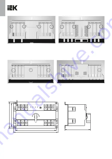
Ðèñóíîê
/ Figure
6
–
Âèä
ñïåðåäè
è
âèä
ñçàäè
ÀÂÐ
-1 STANDARD
/
Back and front view
of AVR-1 STANDARD
Ðèñóíîê / Figure7 – Âèä ñïåðåäè è âèä ñçàäè ÀÂÐ-2 LITE / Back and front view of AVR-2 LITE
Ðèñóíîê /
Figure 8
1
7
125
13
229248
E
5
K
ARAT
Страница 1: ...KARAT IEK 400 50 004 2011 020 2011 037 2016 IEC 60947 6 1 5 C 40 2 17516 1 2000 6 90 50 40 C 90 20 C 1 2 3 1 STANDARD 1 2 LITE 2 1 STANDARD 1 KARAT RU...
Страница 2: ...2 3 2 LITE 4 5 MANU 1 2 1 STANDARD T1 T2 1 STANDARD 2 LITE 4 1 STANDARD UI I UII II ON ON KARAT...
Страница 3: ...3 1 1 2 LITE ON ON 2 LITE 5 8 5 8 6 9 10 1 STANDARD 9 6 KARAT...
Страница 4: ...4 1 5 6 1 3 23216 20 C 40 C 20 C 40 C 50 40 C 90 20 C 7 15 KARAT...
Страница 5: ...technical data of integral circuit breakers are listed in table 2 In automatic mode the AVR is switched from the primary input to the reserve one and vice versa should be carried out using the contro...
Страница 6: ...input voltage indicator position indicator of main contact group of VA standby input If there is voltage on the main input the red LED of the main input UI I is on If there is voltage on the standby i...
Страница 7: ...espond to the diagram shown in figure 9 Completeness of set Delivery set of AVR is listed in table 6 Safety measures Mounting and commissioning of the AVR should be carried out only by qualified elect...
Страница 8: ...he AVR must be disposed Disposal of AVR is carried out by transferring to organizations engaged in the processing of secondary raw materials Service life and manufacturer s warranties The warranty per...
Страница 9: ...ation and busbars Repairability Repairable Rated duty Continuous Location and type of fuses used for control circuits F2AL250V special connectors on the case F2AL250V the connectors are soldered on th...
Страница 10: ...in a clamp pcs 2 Continuation of table 2 Table 3 Parameters Value Version 1 STANDARD AVR 1 STANDARD 2 LITE AVR 2 LITE Operating voltage range controller V AC 175 265 From 175 to 265 160 265 From 160 t...
Страница 11: ...tching with automatic reset manual switching generator triggering mode Automatic switching with automatic reset manual switching Control of phase adhesioh phase sequence phase unbalance No Lower limit...
Страница 12: ...the clips to remove the upper part of the case 5 clips circled in figure 7 5 2 Remove AVR covers 2 pcs Remove AVR cover 6 4 Unscrew the screws on the sides of the AVR case 4 pcs 7 Slide enclosure wit...
Страница 13: ...main input from the reserve if there is power on the main input Incorrect connection diagram 9 Verify the connection diagrams The connection diagram should be as shown in Figure 9 Verify the connecti...
Страница 14: ...f the integral circuit breaker of the reserve input 6 switch from automatic to manual operation mode 7 regulator for setting the delay time for switching from backup to primary input 8 manual switch h...
Страница 15: ...ails and there is no reserve voltage input contacts 503 and 501 are closed while contacts 503 and 502 are open and give a signal to start the generator After starting the generator the AVR automatical...
Страница 16: ...r AC 220 V 5 101 common null line for the indicator 102 signal output to the external indicator of the voltage presence at the primary input 103 signal output to the external indicator of the position...
Страница 17: ...Figure 6 1 STANDARD Back and front view of AVR 1 STANDARD Figure7 2 LITE Back and front view of AVR 2 LITE Figure 8 17 125 113 229 248 E 5 KARAT...
Страница 18: ...Circuit diagram of AVR 2 LITE KARAT 101 102 201 202 301 302 303 401 402 403 501 502 503 601 602 603 604 A1B1 C1 A2B2 C2 A B C load N primary input N QF1 QF2 primary input A1 B1 C1 A2 B2 C2 A B C load...