WSB-G41A CPU Card
Page 55
Step 2:
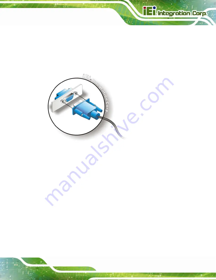
Align the VGA connector
. Align the male DB-15 connector on the VGA screen
cable with the female DB-15 connector on the external peripheral interface.
Step 3:
Insert the VGA connector
.
Once the connectors are properly aligned with the
insert the male connector from the VGA screen into the female connector on the
WSB-G41A. See
.
Figure 4-19: VGA Connector
Step 4:
Secure the connector
. Secure the DB-15 VGA connector from the VGA
monitor to the external interface by tightening the two retention screws on either
side of the connector.
Step 0:
4.7 Software Installation
All the drivers for the WSB-G41A are on the CD that came with the system. To install the
drivers, please follow the steps below.
Step 1:
Insert the CD into a CD drive connected to the system.
Содержание WSB-G41A-R11
Страница 11: ...WSB G41A CPU Card Page xi Table 5 1 BIOS Navigation Keys 60...
Страница 13: ...WSB G41A CPU Card Page 1 Chapter 1 1 Introduction...
Страница 21: ...WSB G41A CPU Card Page 9 Chapter 2 2 Packing List...
Страница 26: ...WSB G41A CPU Card Page 14 Chapter 3 3 Connectors...
Страница 47: ...WSB G41A CPU Card Page 35 Chapter 4 4 Installation...
Страница 70: ...WSB G41A CPU Card Page 58 Chapter 5 5 BIOS...
Страница 107: ...WSB G41A CPU Card Page 95 Appendix A A BIOS Options...
Страница 110: ...WSB G41A CPU Card Page 98 Appendix B B Terminology...
Страница 114: ...WSB G41A CPU Card Page 102 Appendix C C Watchdog Timer...
Страница 117: ...WSB G41A CPU Card Page 105 Appendix D D Digital I O Interface...
Страница 119: ...WSB G41A CPU Card Page 107 Appendix E E Hazardous Materials Disclosure...


