WSB-G41A CPU Card
Page 52
Step 4:
Attach the bracket to the chassis
. The USB 2.0 connectors are attached to a
bracket. To secure the bracket to the chassis please refer to the installation
instructions that came with the chassis.
Step 0:
4.6 External Peripheral Interface Connection
This section describes connecting devices to the external connectors on the WSB-G41A.
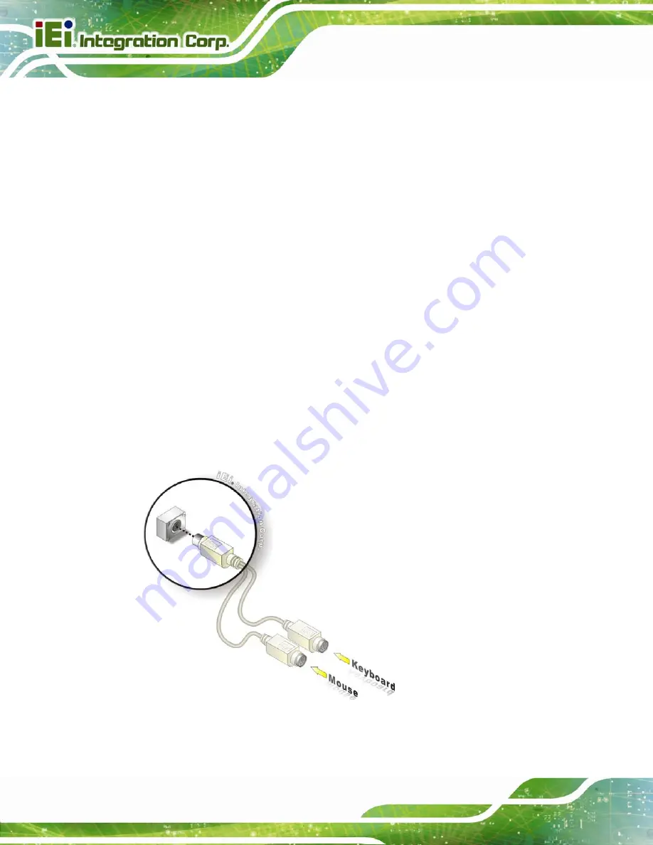
4.6.1 PS/2 Y-Cable Connection
The WSB-G41A has a PS/2 connector on the external peripheral interface panel. The dual
PS/2 connector is connected to the PS/2 Y-cable that came with the WSB-G41A. One of
the PS/2 cables is connected to a keyboard and the other to a mouse to the system.
Follow the steps below to connect a keyboard and mouse to the WSB-G41A.
Step 1:
Locate the dual PS/2 connector
. The location of the PS/2 connector is shown
in
Chapter 3
.
Step 2:
Insert the keyboard/mouse connector
.
Insert the PS/2 connector on the end
of the PS/2 y-cable into the external PS/2 connector. See Figure 4-16.
Figure 4-16: PS/2 Keyboard/Mouse Connector
Содержание WSB-G41A-R11
Страница 11: ...WSB G41A CPU Card Page xi Table 5 1 BIOS Navigation Keys 60...
Страница 13: ...WSB G41A CPU Card Page 1 Chapter 1 1 Introduction...
Страница 21: ...WSB G41A CPU Card Page 9 Chapter 2 2 Packing List...
Страница 26: ...WSB G41A CPU Card Page 14 Chapter 3 3 Connectors...
Страница 47: ...WSB G41A CPU Card Page 35 Chapter 4 4 Installation...
Страница 70: ...WSB G41A CPU Card Page 58 Chapter 5 5 BIOS...
Страница 107: ...WSB G41A CPU Card Page 95 Appendix A A BIOS Options...
Страница 110: ...WSB G41A CPU Card Page 98 Appendix B B Terminology...
Страница 114: ...WSB G41A CPU Card Page 102 Appendix C C Watchdog Timer...
Страница 117: ...WSB G41A CPU Card Page 105 Appendix D D Digital I O Interface...
Страница 119: ...WSB G41A CPU Card Page 107 Appendix E E Hazardous Materials Disclosure...


