WAFER-PV-D5252/D4252/N4552 SBC
Page 56
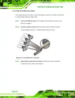
4.7.4 Four Serial Port Connector
The 40-pin serial port connector connects the board connector to four DB-9 connectors.
To install, please follow the steps below.
Step 1:
Locate the COM connector
. The locations of the COM port connectors are
shown in Chapter 4.
Step 2:
Insert the cable connector.
Align the cable connector with the onboard
connector. Make sure pin 1 on the board and connector line up..
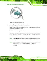
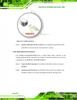
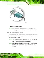
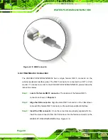
Figure 4-14: Four Serial Port Connector
Step 3:
Secure the serial ports to the chassis
. Tighten the screws on the DB-9
connectors to secure them to the chassis.
Step 0:
Содержание WAFER-PV-D4252
Страница 14: ...WAFER PV D5252 D4252 N4552 SBC Page 1 Chapter 1 1 Introduction...
Страница 18: ...WAFER PV D5252 D4252 N4552 SBC Page 5 Figure 1 4 Dimensions with Heatsink mm...
Страница 22: ...WAFER PV D5252 D4252 N4552 SBC Page 9 Chapter 2 2 Packing List...
Страница 26: ...WAFER PV D5252 D4252 N4552 SBC Page 13 Chapter 3 3 Connector Pinouts...
Страница 52: ...WAFER PV D5252 D4252 N4552 SBC Page 39 Chapter 4 4 Installation...
Страница 76: ...WAFER PV D5252 D4252 N4552 SBC Page 63 Chapter 5 5 BIOS...
Страница 104: ...WAFER PV D5252 D4252 N4552 SBC Page 91 Appendix A A BIOS Options...
Страница 107: ...WAFER PV D5252 D4252 N4552 SBC Page 94 Appendix B B One Key Recovery...
Страница 135: ...WAFER PV D5252 D4252 N4552 SBC Page 122 Appendix C C Terminology...
Страница 139: ...WAFER PV D5252 D4252 N4552 SBC Page 126 Appendix D D Hazardous Materials Disclosure...


