WAFER-945GSELVDS2
Page 62
4.8.5 USB Cable
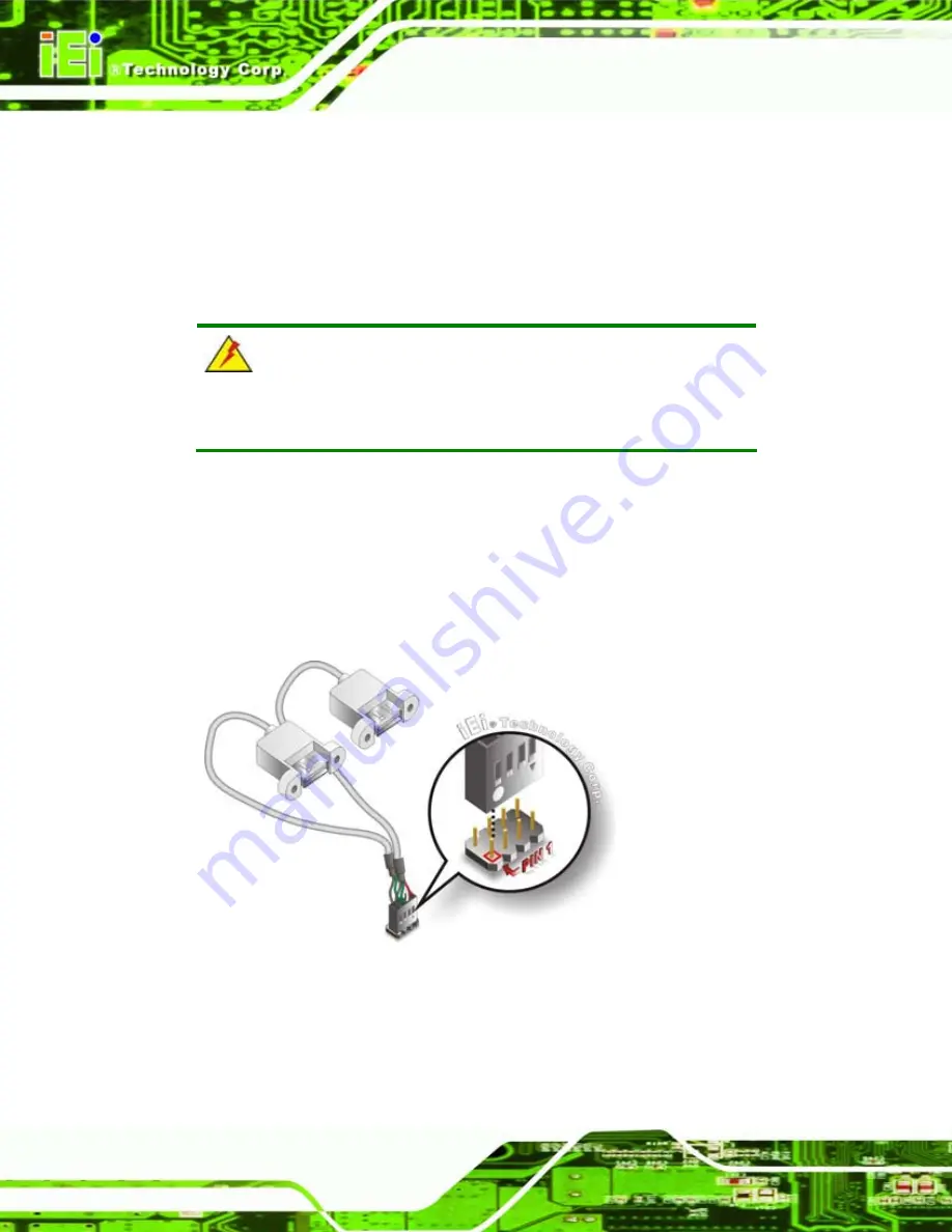
The WAFER-945GSELVDS2 is shipped with a dual port USB 2.0 cable. To connect the
USB cable connector, please follow the steps below.
Step 1:
Locate the connectors
. The locations of the USB connectors are shown in
Chapter 3
.
WARNING:
If the USB pins are not properly aligned, the USB device can burn out.
Step 2:
Align the connectors
. The cable has two connectors. Correctly align pin 1on
each cable connector with pin 1 on the WAFER-945GSELVDS2 USB connector.
Step 3:
Insert the cable connectors
. Once the cable connectors are properly aligned
with the USB connectors on the WAFER-945GSELVDS2, connect the cable
connectors to the on-board connectors. See
Figure 4-16: Dual USB Cable Connection
Step 4:
Attach the USB connectors to the chassis
. The USB 2.0 connectors each of
two retention screw holes. To secure the connectors to the chassis please refer
to the installation instructions that came with the chassis
.
Step 0:
Содержание WAFER-945GSELVDS2
Страница 2: ...WAFER 945GSELVDS2 Page ii Revision Date Version Changes 24 September 2009 1 00 Initial release...
Страница 13: ...WAFER 945GSELVDS2 Page 1 Chapter 1 1 Introduction...
Страница 18: ...WAFER 945GSELVDS2 Page 6 Figure 1 4 Bottom Dimensions mm Figure 1 5 External Interface Panel Dimensions mm...
Страница 20: ...WAFER 945GSELVDS2 Page 8 Chapter 2 2 Unpacking...
Страница 24: ...WAFER 945GSELVDS2 Page 12 Chapter 3 3 Connectors...
Страница 52: ...WAFER 945GSELVDS2 Page 40 Chapter 4 4 Installation...
Страница 82: ...WAFER 945GSELVDS2 Page 70 Chapter 5 5 BIOS...
Страница 123: ...WAFER 945GSELVDS2 Page 111 Appendix A A BIOS Options...
Страница 127: ...WAFER 945GSELVDS2 Page 115 Appendix B B Terminology...
Страница 131: ...WAFER 945GSELVDS2 Page 119 Appendix C C Digital I O Interface...
Страница 134: ...WAFER 945GSELVDS2 Page 122 Appendix D D Watchdog Timer...
Страница 137: ...WAFER 945GSELVDS2 Page 125 Appendix E E Hazardous Materials Disclosure...


