WAFER-8523 User Manual
Page 47
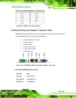
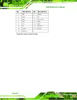
PIN DESCRIPTION PIN
DESCRIPTION
1 MDI0+
5 MDIA1+
2 MDIA3+
6 MDIA2+
3 MDIA2-
7 MDIA0-
4 MDIA1-
8 MDIA0+
Table 4-20: LAN Pinouts
Figure 4-20: RJ-45 Ethernet Connector
The RJ-45 Ethernet connector has two status LEDs, one green and one yellow. The green
LED indicates activity on the port and the yellow LED indicates the port is linked. See
7
Table 4-21
.
STATUS
DESCRIPTION
STATUS
DESCRIPTION
GREEN Activity
YELLOW Linked
Table 4-21: RJ-45 Ethernet Connector LEDs
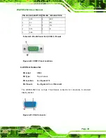
4.4.3 Reset Button Switch
CN Label:
SW1
CN Type:
2-pin wafer (1x2)
CN Location:
See
Figure 4-21
CN Pinouts:
See
Table 4-22
The reset button switch enables users to reboot the system when the system is turned on.
Содержание WAFER-8523
Страница 16: ...WAFER 8523 User Manual Page 1 Chapter 1 1 Introduction...
Страница 22: ...WAFER 8523 User Manual Page 7 Chapter 2 2 Detailed Specifications...
Страница 36: ...WAFER 8523 User Manual Page 21 Chapter 3 3 Unpacking...
Страница 40: ...WAFER 8523 User Manual Page 25 Chapter 4 4 Connectors...
Страница 66: ...WAFER 8523 User Manual Page 51 Chapter 5 5 Installation...
Страница 91: ...WAFER 8523 User Manual Page 76 Chapter 6 6 BIOS Screens...
Страница 127: ...WAFER 8523 User Manual Page 112 Chapter 7 7 Software Drivers...
Страница 154: ...WAFER 8523 User Manual Page 139 Appendix A A BIOS Options...
Страница 157: ...WAFER 8523 User Manual Page 142 376H Load Optimal Defaults 947H111 377H Load Failsafe Defaults 948H111...
Страница 158: ...WAFER 8523 User Manual Page 143 Appendix B B Terminology...
Страница 162: ...WAFER 8523 User Manual Page 147 Appendix C C Watchdog Timer...
Страница 165: ...WAFER 8523 User Manual Page 150 Appendix D D Compatibility...
Страница 168: ...WAFER 8523 User Manual Page 153 Appendix E E Hazardous Materials Disclosure...
Страница 172: ...WAFER 8523 User Manual Page 157 Index...


