UPC-F12C-ULT3 Panel PC
Page 23
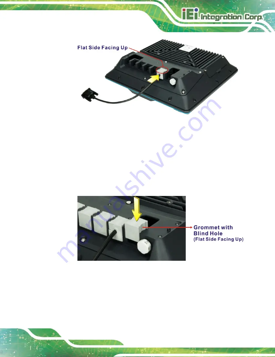
Figure 3-12: Installing Grommet
Step 6:
Repeat
Step 3 ~ Step 5
to connect necessary cables and install grommets.
Step 7:
Re-install the I/O cover onto the rear panel of the UPC-F12C-ULT3 by using six
previously removed screws.
Step 8:
With the flat side facing upward, insert grommets with blind hole into those holes
with no cables installed.
Figure 3-13: Installing Grommet with Blind Hole
Step 9:
Re-install the top panel of the I/O cover by using seven previously removed
screws.
Step 0:
Содержание UPC-F12C-ULT3
Страница 15: ...UPC F12C ULT3 Panel PC Page 1 1 Introduction Chapter 1 ...
Страница 23: ...UPC F12C ULT3 Panel PC Page 9 2 Unpacking Chapter 2 ...
Страница 27: ...UPC F12C ULT3 Panel PC Page 13 3 Installation Chapter 3 ...
Страница 43: ...UPC F12C ULT3 Panel PC Page 29 4 BIOS Setup Chapter 4 ...
Страница 75: ...UPC F12C ULT3 Panel PC Page 61 Chapter 5 5 Interface Connectors ...
Страница 95: ...UPC F12C ULT3 Panel PC Page 81 Appendix A A Regulatory Compliance ...
Страница 100: ...UPC F12C ULT3 Panel PC Page 86 B Safety Precautions Appendix B ...
Страница 106: ...UPC F12C ULT3 Panel PC Page 92 C BIOS Menu Options Appendix C ...
Страница 109: ...UPC F12C ULT3 Panel PC Page 95 Appendix D D Watchdog Timer ...
Страница 112: ...UPC F12C ULT3 Panel PC Page 98 Appendix E E Hazardous Materials Disclosure ...


